I'd be keen to hear how this integration is going 6 years on.....
I've moved into a new home and it has an HRV with the newer touch screen control panel, will be interesting to hear thoughts on if this can still be integrated?
I'd be keen to hear how this integration is going 6 years on.....
I've moved into a new home and it has an HRV with the newer touch screen control panel, will be interesting to hear thoughts on if this can still be integrated?
Hey Tommy,
Still going strong, although am still running the original control panel. I don't know if the newer touch screen panel also means a newer controller and therefore different serial messages. If it's just a control panel upgrade, but same data sent, then it should just work.
I'd suggest giving it a try. I wrote an instructable for it which may help...
I've moved into a new home and it has an HRV with the newer touch screen control panel, will be interesting to hear thoughts on if this can still be integrated?
I've also just moved into a house with a c.15 year old steel box HRV ... that doesn't work :-( A service guy came, concluded the control panel was broken, and offered to install a modern one (for $500!). It plugs into the same RJ12 cable, so at least some modern HRV kit still uses the same signalling.
I'm just building this project so thanks to those who have put so much work into it. Has anyone used it to completely replace and throw away the HRV controller. The HRV one does some pretty dumb stuff sometimes, especially when you are trying to heat a room even though it thinks its too warm in the house. I'd love to feed in humidity data to make it a much smarter system.
Just as an update on this, I've made quite a bit of progress in working with the HRV system. I discovered that if using the Wemos D1, it runs off 5V and handled 5V ttl, so you can wire it up directly to the HRV system with no external boards or level shifters. I've also had success in controlling the HRV, in particular, my goal was to replace the control panel with my own board which would be controlled by my home automation system so that it did not clash with other heating.
The trick turned out to be to use the half duplex mode in the ESP software serial library which can flick the same pin between rx and tx.
So I can now send a command to the fan controller, set the speed of the fan and then wait for the reply with the temperature, all on the same wire and pin.
I'm tidying up the code a bit and will post photos and code here with instructions on how to do a much simpler implementation than what is described here.
Wow that would be great!
I am so tired of the standard logic in my ultra-old HRV, would love to replace it with something custom that would make more sense to me. Such as run ventilation at higher fan speed at late night time and especially early morning, when moisture level in bedrooms is the highest...
My pet peeve is that it can be running flat out to cool down your house while you have the heating cranked.
I'll be implementing this as basically a remote fan control and a way to get the roof temperature out, and then you can shift all the logic to your home automation system which should be aware of humidity and temperatures.
Since we got a ducted heat pump I just have the HRV on a basic plug timer to turn it of/on so it runs for 2 hours a day just to get some fresh air in... I'd also be keep to see your approach especially to getting "control" of the HRV.
Which version do you have? Mine is one with a little touch screen controller.
ok, here is some code, before I radically customise it to my needs.
This code receives a UDP message on port 1111 containing the fan speed you want to set 0x00 is off and 0x64 is full speed.
To use it,
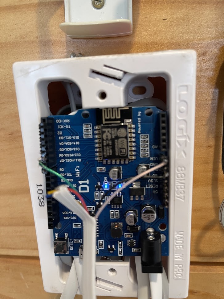
- just connect the Black wire from your HRV fan controller in the roof to ground on the Wemos D1 - connect the white wire to VIN - connect the green wire to pin D5
Thats it, no resistors, or power converters or TTL converters needed, the Wemos D1 works on 5V.
The last step is to throw away your HRV control panel, don't try to run it at the same time, it just wont work, you can only have one master on the bus and your arduino is now going to be the boss.
I have a TFT screen on order so when that arrives I'm going to modify this code to display HRV like things on the screen and mount it all back under the HRV panel, may even connect up some buttons.
// TTL hrvSerial data array, bIndex, bIndex of checksum and temperature int iLoop; byte inData[10]; byte bIndex; byte bChecksum; bool bStarted = false; bool bEnded = false;
int iTotalDelay = 0;
// Temperature for sending to MQTT float fHRVTemp; int iHRVControlTemp; int iHRVFanSpeed;
byte targetFanSpeed = 0x00; //we will send the fan the speed we want it to run at
void setup() { // put your setup code here, to run once: //hrvSerial.begin(1200); hrvSerial.begin(1200, SWSERIAL_8N1, D6, D6, false, 256); hrvSerial.enableIntTx(false); // Debug USB Serial Serial.begin(115200);
ss->enableTx(true); //this is the magic, tell the arduino to switch the pin into TX mode so we can send and receive on the same wire. //while (Serial.available()) { Serial.println("send: "); int i; ss->write(MSGSTARTSTOP); //send start message first for(i=0; i<sizeof(message); i++){ ss->write(message[i]); Serial.print(message[i],HEX); //send the stuff its expecting including our new fan speed } ss->write(bCalc);//send checksum ss->write(MSGSTARTSTOP); //send stop bit
} ss->enableTx(false); //this is the magic, tell the board to start listening on the same pin we just wrote to Serial.println("wait");
// wait 1 second for the reply from SOftwareSerial if any delay(1000); if (ss->available()) { Serial.print(PSTR("\nResult:")); while (ss->available()) { ch = (byte)ss->read(); Serial.print(ch < 0x10 ? PSTR(" 0") : PSTR(" ")); Serial.print(ch, HEX); int inChar = int(ch);
if (inChar == MSGSTARTSTOP || bIndex > 8) { // Start if first time we've got the message if (bIndex == 0) { Serial.println("Started Block"); bStarted = true; } else { bChecksum = bIndex-1; bEnded = true; break; } }
if (bStarted == true) { // Double check we actually got something if (sizeof(inChar) > 0) { Serial.print(inChar, HEX); inData[bIndex] = inChar; bIndex++; } } myDelay(1); } Serial.println(); }
String sHexPartOne; String sHexPartTwo; int iPos;
// Pull data out of the array, position 0 is 0x7E (start and end of message) for (int iPos=1; iPos <= bIndex; iPos++) {
// Position 1 defines house or roof temperature if (iPos==1) { eTempLoc = (char) inData[iPos]; }
// Position 2 and 3 are actual temperature, convert to hex if (iPos == 2) { sHexPartOne = decToHex(inData[iPos], 2); } if (iPos == 3) { sHexPartTwo = decToHex(inData[iPos], 2); }
} // Concatenate first and second hex, convert back to decimal, 1/16th of dec + rounding // Note: rounding is weird - it varies between roof and house, MQTT sub rounds to nearest 0.5 fHRVTemp = hexToDec(sHexPartOne + sHexPartTwo); fHRVTemp = (fHRVTemp * 0.0625); int iHRVTemp; iHRVTemp = (int) ((fHRVTemp * 2) + 0.5); fHRVTemp = (float) iHRVTemp / 2; String pubString; pubString = String(fHRVTemp);
Are you subscribed to our RSS feed? You can download the latest headlines and summaries from our stories directly
to your computer or smartphone by using a feed reader.