Geekzone: technology news, blogs, forums
Guest
Welcome Guest.
You haven't logged in yet. If you don't have an account you can register now.


samgdan

160 posts

Master Geek
+1 received by user: 4


#272805 16-Jul-2020 22:03
Send private message

Hi,


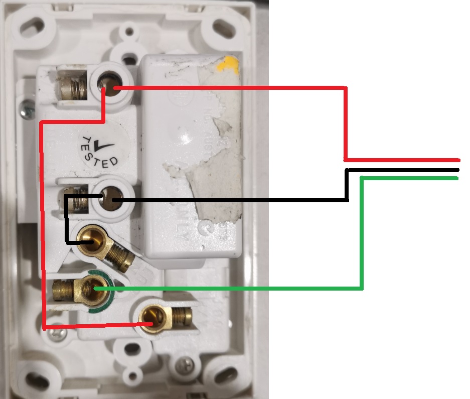
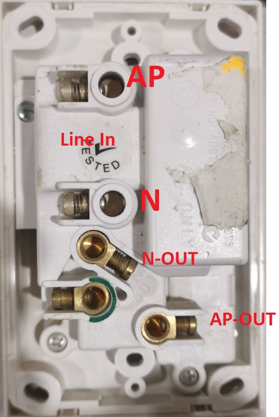
While I was installing some insulation and I saw the RCD powerpoint that is in the bathroom and I noticed something that called my attention.


The photo is for reference but I do believe the RCD is acting as a normal powerpoint.


The two top connectors are not in use, is that correct?


i know to fix this I need an electrician but I curios to know how this should be connected (as long if it is wrong)


Thanks


sounds good to have the sound working

View this topic in a long page with up to 500 replies per page Create new topic
 1 | 2
DarthKermit
5346 posts

Uber Geek
+1 received by user: 3317

Trusted

  #2524434 16-Jul-2020 22:05
Send private message

The other two terminals are to allow for more power points to be wired in downstream and also be RCD protected.


samgdan

160 posts

Master Geek
+1 received by user: 4


  #2524435 16-Jul-2020 22:16
Send private message

Should the connection be like this? Based from what I found on the internet, all cables at least 2.5mm?


sounds good to have the sound working

samgdan

160 posts

Master Geek
+1 received by user: 4


  #2524436 16-Jul-2020 22:17
Send private message

DarthKermit:


The other two terminals are to allow for more power points to be wired in downstream and also be RCD protected.


I think that is the idea of this type of powerpoint (to be RCD protected) otherwise a normal powerpoint would be installed.


what do you think about my previous reply? is that connection correct?


sounds good to have the sound working


Bung
6733 posts

Uber Geek
+1 received by user: 2926

Subscriber

  #2524443 16-Jul-2020 22:44
Send private message

No it is not! The RCD has an input and a protected output and they should not be wired together..

Even though you have an RCD if you add any sockets to the circuit the new work has go be inspected before it is connected.

Edit. You are right in 1st post that wiring is wrong. Without knowing history of the connection it's hard to tell whether it was a mistake or the RCD is faulty and it was a deliberate bodge.

samgdan

160 posts

Master Geek
+1 received by user: 4


  #2524444 16-Jul-2020 22:46
Send private message

Bung: No it is not! The RCD has an input and a protected output and they should not be wired together..

Even though you have an RCD if you add any sockets to the circuit the new work has go be inspected before it is connected.


So the way it's is correct?


sounds good to have the sound working

elpenguino
3576 posts

Uber Geek
+1 received by user: 2938


  #2524450 16-Jul-2020 23:03
Send private message

samgdan:
Bung: No it is not! The RCD has an input and a protected output and they should not be wired together..

Even though you have an RCD if you add any sockets to the circuit the new work has go be inspected before it is connected.


So the way it's is correct?


The way you have drawn it is not correct.


Th drawing from the supplier is correct.


Most of the posters in this thread are just like chimpanzees on MDMA, full of feelings of bonhomie, joy, and optimism. Fred99 8/4/21


Shop now at Mighty Ape (affiliate link).
samgdan

160 posts

Master Geek
+1 received by user: 4


  #2524455 16-Jul-2020 23:20
Send private message

I understand but the way that currently is connected (my first post) is correct?
Is the RDC function of the PowerPoint working in that way?


sounds good to have the sound working

elpenguino
3576 posts

Uber Geek
+1 received by user: 2938


  #2524460 16-Jul-2020 23:29
Send private message

I can't say as I can't read the markings in your photo. I'm looking for 'line in' or similar.


Most of the posters in this thread are just like chimpanzees on MDMA, full of feelings of bonhomie, joy, and optimism. Fred99 8/4/21


Ruphus
469 posts

Ultimate Geek
+1 received by user: 181


  #2524462 16-Jul-2020 23:34
Send private message

@gregmcc, care to wade in here?

SomeoneSomewhere
1882 posts

Uber Geek
+1 received by user: 1086

Lifetime subscriber

  #2524463 16-Jul-2020 23:35
Send private message

Your photo is conveniently taken at an angle so that the lettering molded into the plastic is illegible...


Your diagram of how it is currently wired is incorrect, and will not provide protection. You should be able to test this - pushing the test button will not cut the power.


Your proposed wiring diagram for rewiring is also incorrect. You need to wire the incoming power to the top two terminals and earth. If you have a second cable at the socket, leading to the rest of the circuit, you would connect this to the lower terminals as the manual shows.


Those two lower terminals came from the factory with a bright orange sticker saying 'do not use these unless...' on them. Someone really screwed up. They also come with a neon wired into them for the 'power available' light.


I think messing around with RCDs might be outside the scope of ECP51; you might need a sparky for this. I can't be bothered to go read it...


samgdan

160 posts

Master Geek
+1 received by user: 4


  #2524465 16-Jul-2020 23:36
Send private message

elpenguino:


I can't say as I can't read the markings in your photo. I'm looking for 'line in' or similar.


it is like this


LINE IN  AP and N are not in use currently


the other tree connectors, yes.


please be aware that this is a sample photos, but the RCD that I have is exactly the same.


sounds good to have the sound working


Support Geekzone with one-off or recurring donations Donate via PressPatron.
Fred99
13684 posts

Uber Geek
+1 received by user: 10018


  #2524466 16-Jul-2020 23:39
Send private message

I'm not a sparky, but I'd very very surprised if the position of the terminals wasn't in the same order as the schematic, and as such with the phase connected directly to the output socket, then nope - the socket won't be RCD protected.


SomeoneSomewhere
1882 posts

Uber Geek
+1 received by user: 1086

Lifetime subscriber

  #2524467 16-Jul-2020 23:43
Send private message

Fred99:


I'm not a sparky, but I'd very very surprised if the position of the terminals wasn't in the same order as the schematic, and as such with the phase connected directly to the output socket, then nope - the socket won't be RCD protected.


Correct, but schematics are not always that nice and can sometimes be flipped left-right (are you looking at it from the front or back?), or rotated.


I believe on these the line out terminals are directly connected to the front face socket. The US had enough trouble with miswires that they now use two double-pole switches, so the socket is isolated from both line-in and line-out when it's tripped, and they trip when miswired. We mostly skipped this by making it mandatory for all new domestic socket circuits to have the RCD at the switchboard.


samgdan

160 posts

Master Geek
+1 received by user: 4


  #2524468 16-Jul-2020 23:46
Send private message

SO In summary:


the current way that it is connected works but it is NOT  RCD protected.

The below is the correct way to have the powerpoint RCD protected.


Can someone confirm if that is correct?


sounds good to have the sound working

SomeoneSomewhere
1882 posts

Uber Geek
+1 received by user: 1086

Lifetime subscriber

  #2524478 17-Jul-2020 01:55
Send private message

Yes. This assumes there is only one cable at the outlet.


 1 | 2
View this topic in a long page with up to 500 replies per page Create new topic


Geekzone Live »

Try automatic live updates from Geekzone directly in your browser, without refreshing the page, with Geekzone Live now.


Are you subscribed to our RSS feed? You can download the latest headlines and summaries from our stories directly to your computer or smartphone by using a feed reader.