Geekzone: technology news, blogs, forums
Guest
Welcome Guest.
You haven't logged in yet. If you don't have an account you can register now.


aucklander

478 posts

Ultimate Geek
+1 received by user: 11


#289041 9-Aug-2021 12:46
Send private message

Hi,


I started to write a much longer story about my question but the browser crashed on me, so I hope I can do it with a much shorter version, no pictures included...


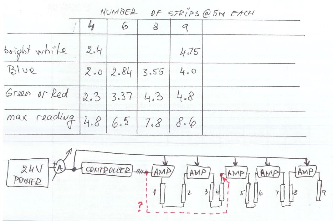
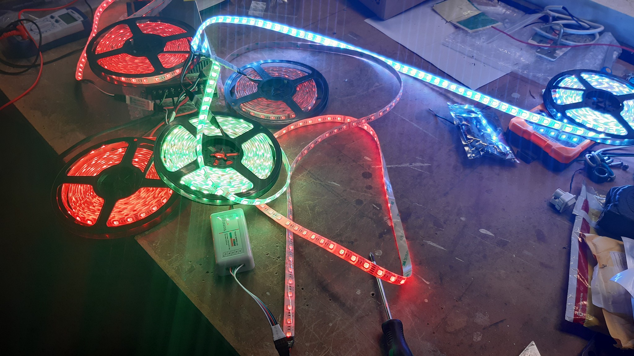
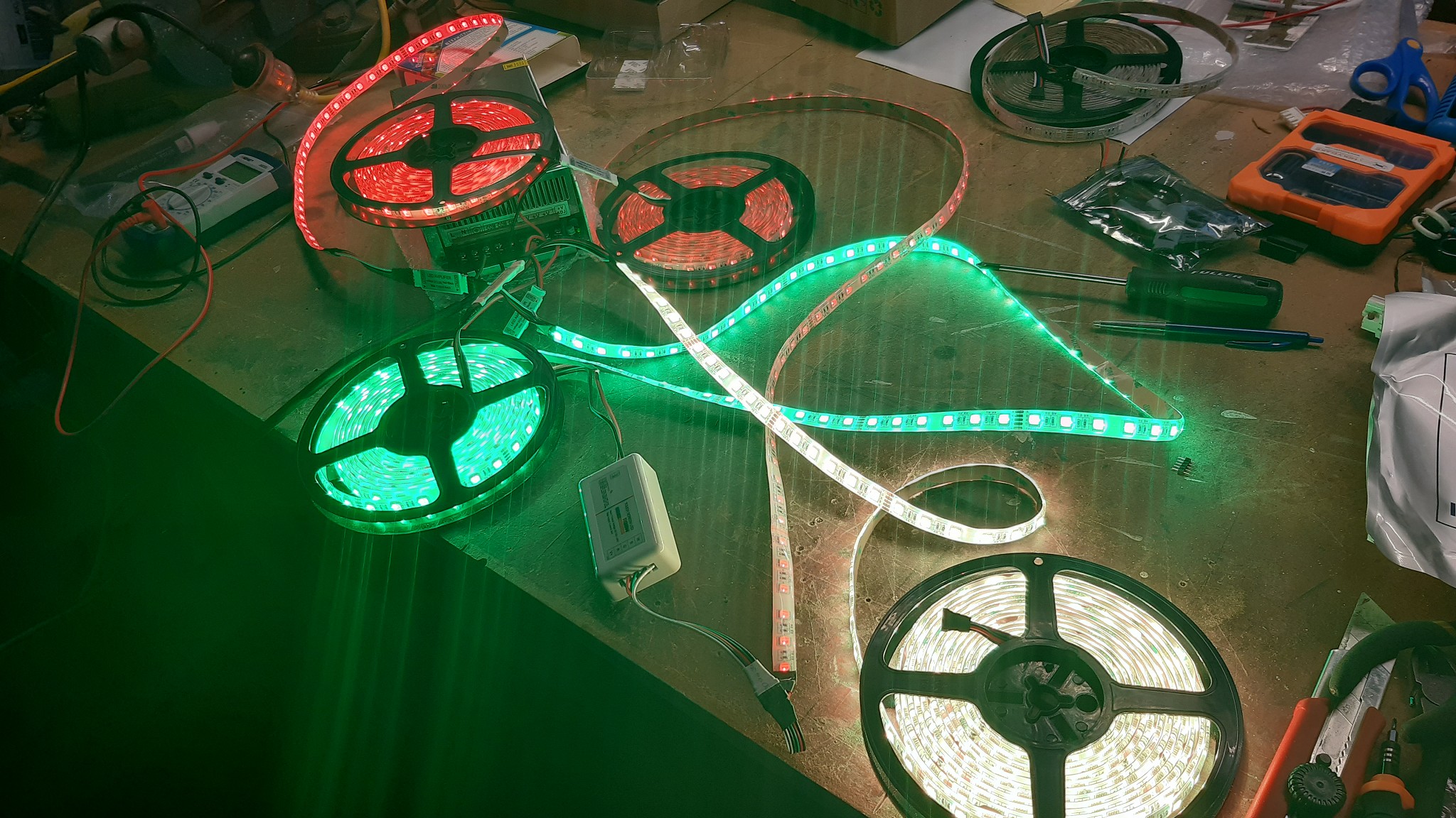
Wiring RGBW strips, need to achieve 9x 5m strips in line. I am using "mini-amplifiers" and after connecting 4-5 strips the colour at the end is totally different from the first 1-2 strips.See pictures below, colour is supposed to be red, tha last two show different colour. Connecting the strips or the amplifiers directly fixes the problem, it gets all strange only when I start having 4-5 strips connected...


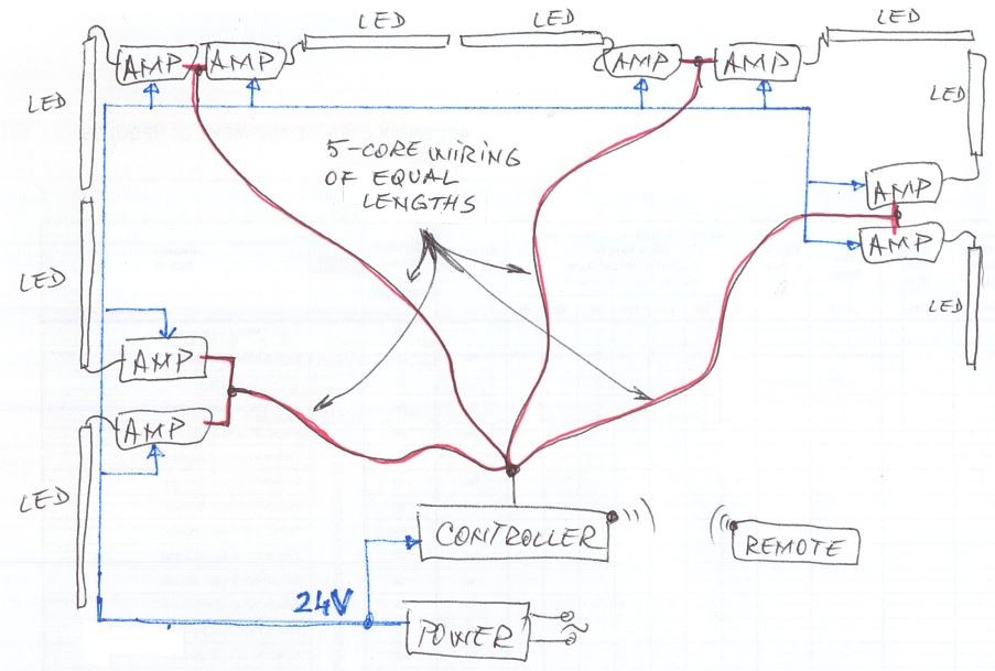
I see there are two ways to connect the amplifiers:


[1] - "in series" strip - ampl - strip - ampl - strip , and so on, with power feed wired to each of the amplifiers. This is what I tried, and results were not great


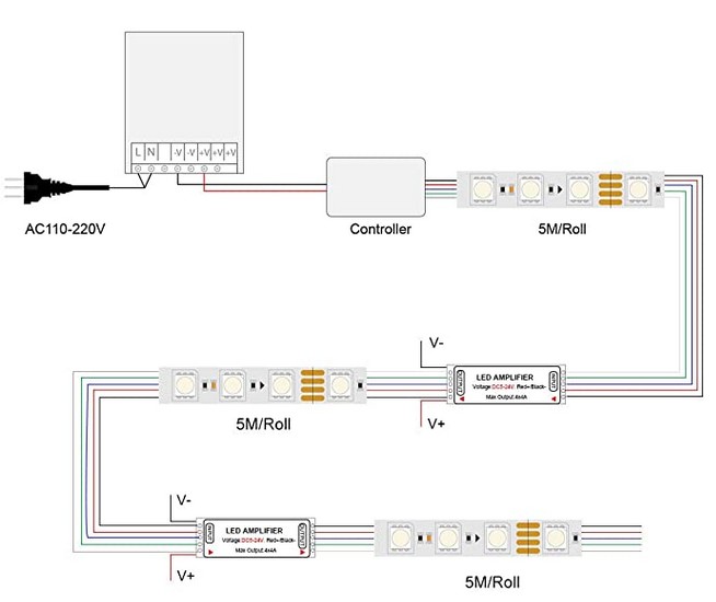
[2] - run the signal from the controller to first amplifier, then loop to the next amplifier and so on, each amplifier also gets power and it only feeds one strip


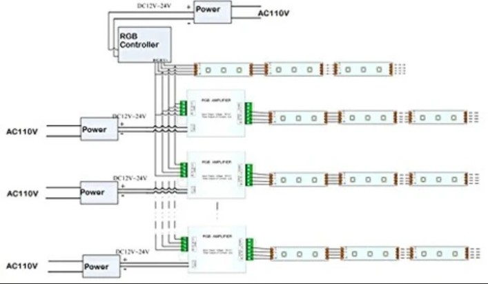
Is it better in option [2]? Is that the recommended setup?


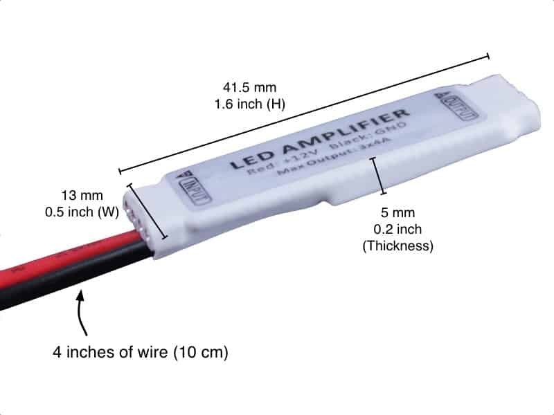
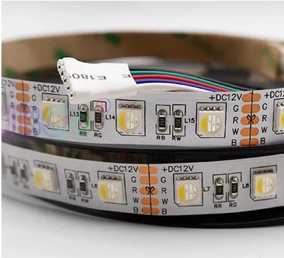
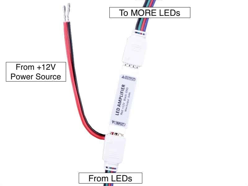
I am using these amplifiers:


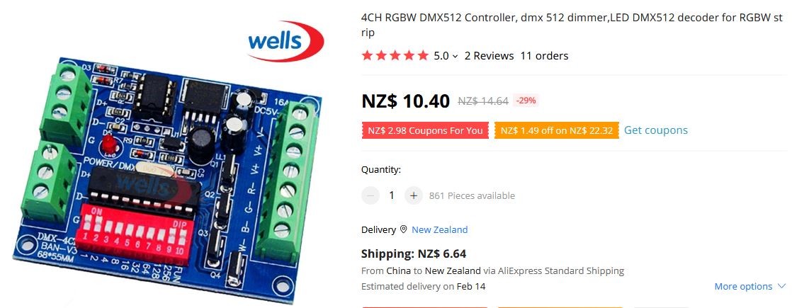
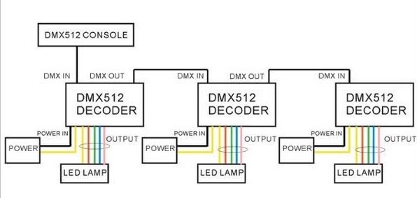
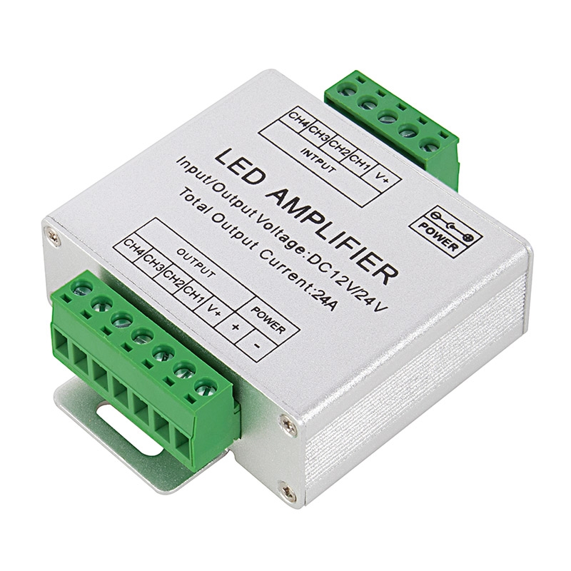
should I look at using these maybe? Are they better quality?


RGBW-A6 RGB Amplifier | Super Bright LEDs


Is my issue something to do with the distance between the controller and various amplifiers? (signal degrading with the distance, then amplified - but every time the error is also amplified? How can I work around that and have all strips of same colour?


Many thanks in advance.


Create new topic
frankv
5705 posts

Uber Geek
+1 received by user: 3666

Lifetime subscriber

  #2757326 9-Aug-2021 16:33
Send private message

The power supply voltage is lower at the tail end of each strip than at the controller end, because the wires inside the strips are very thin. So if you just connect another strip (or 2 or 3)  on, it won't work because the second or third strip's voltage will be too low. This will be worse if all the LEDs are at full brightness. The solution is to run a pair of heavier (22AWG or so if you have 12V strips) wires from the power supply direct (i.e. from *before* the controller) to V+ and V- between the strips... i.e. to an "amplifier". The amplifiers will almost certainly not amplify anything. They just act as a convenient point to inject your power supply. You don't need amplifiers on the signal lines, because the strips are controlled digitally. Each LED controller chip (for a group of three LEDs) outputs a new, full-strength signal to the next LED controller chip.


It looks like you have 12V strips? Which should be fairly immune to voltage drop. But it may be that your power supply isn't up to the job. Possibly all the LEDs are consuming more amps than your supply can produce. When that happens, the output voltage will start to drop. If you figure 15W/m, you have 75W per 5m strip, which is a bit over 6A. For 6A, you want 22AWG or thicker. If you have 4 strips, that's 24A, which is a lot. Check your supply's label and see if it's good enough. Beware that AliExpress (& BangGood and all the rest) often exaggerate their supplies' capabilities. If you have a multimeter, check the voltage between V+ and V- at each "amplifier" whilst the LEDs are on.


If you use 22AWG wire, you will need to run a separate pair of wires from the supply to each amplifier... you cannot daisy-chain one pair of wires onto another. So you will need up to 30m (5 + 10 + 15) of wire for 4 strips. If you want to daisy-chain, you could use 5m of 14AWG wire for the first link, 5m of 18AWG for the next one, 5m of 22AWG for the third one.


That bottom "amplifier" claims to handle 24A, but I'll bet those green screw terminals are only good for 6A, and would be very surprised if they can even take 14AWG wire. I'd guess that 24A through that would be a fire waiting to happen.


If you wire up all the controllers in parallel as in option 2, it should work just fine (so long as you don't connect strips in series, your power supplies are all good for 6A, and you have 22AWG wire from the supply to each controller). However, the downside is that you need one mains power outlet per strip, have to buy one power supply per strip, and all the strips will display the same patterns.


richms
29109 posts

Uber Geek
+1 received by user: 10225

Trusted
Lifetime subscriber

  #2757333 9-Aug-2021 16:57
Send private message

There is latency in the amplifiers that will be different on the turn on and off times, as you cascade them it gets worse.


They all need to run from the controller directly like picture 2.


As the voltage drop gets worse because its at the end of the long strip then it will make the effect worse.


Higher PWM frequencies make the problems with these cheap amplifiers worse, lower frequencies make these cheap LED strips even more unbearable.


Richard rich.ms

gregmcc
2173 posts

Uber Geek
+1 received by user: 836

ID Verified
Trusted
Lifetime subscriber

  #2757351 9-Aug-2021 17:02
Send private message

The problem is a volt drop over distance problem.


The way the RGB drivers work is by varying the voltage to R or G or B to achieve the different colours, when you have a long strip there will be volt drop along the conductors, this varies with the load and the length, so what may start out as red at one end will be a different colour at the other end due to the lower voltage.


The solution, less length and where needed more RGB controllers.


The amplifier may not be the solution as it will have a fixed gain and depending on where it is placed the gain may not be enough or even too much.


There is a formula to calculate the cable size, the variable you need to know is the maximum distance and the maximum current -I've had a quick look for it but of hand can't find it.


richms
29109 posts

Uber Geek
+1 received by user: 10225

Trusted
Lifetime subscriber

  #2757353 9-Aug-2021 17:05
Send private message

gregmcc:


The problem is a volt drop over distance problem.


The way the RGB drivers work is by varying the voltage to R or G or B to achieve the different colours, when you have a long strip there will be volt drop along the conductors, this varies with the load and the length, so what may start out as red at one end will be a different colour at the other end due to the lower voltage.


None of these vary voltage at all, they are all crude PWM dimming, most of the controllers have no gamma correction or correction for the turn on times so the lowest brightness is way too bright and they use a naïve 0-255 output directly scaled to 0-100% duty cycle.


Actual proper non flickering control needs a current control and is not found on the cheap aliexpress junk made to drive 12v LED strips that cost a few dollars per meter.


Richard rich.ms

aucklander

478 posts

Ultimate Geek
+1 received by user: 11


  #2852246 17-Jan-2022 13:01
Send private message

I wish to revive this thread if you are still interested,


I agree the components are from Aliexpress but everyone on TradeMe sells the same stuff, only at 3-5 times the price.


I am running 24V system, power supply is 24V / 30A and should suffice for 40m of strip which I want to use.


The strips are RGBW type, rated IP65, will be installed in aluminium channel with opaque diffuser.


Even if the controller and "amplifiers" need to be replaced, I would have to reuse the strips, as they costed way more than the controllers or the $1 amplifiers...


The only issue I have is to identify the proper wiring configuration to get all strips same colour.


Agree, if I just install a mini-amplifier after each strip, the voltage drop of the end of teh strip will cause an error in the second strip colour, then again and again for the next ones, this will never work.


After further research I have come up with these options:


[1]


provide each strip with its own cheap "mini-amplifier" used only as power injection point but wire them directly from the controller in such way that the distance is the same, hopefully resulting in same voltage drop and consequently the same strip colour? This would increase the amount of wiring but would "balance" the voltage drops to each amplifier, which means they will all receive the signal with same "error". This wiring configuration could be achieved, as it would come from a room failry in the center of the area where the LEDS go around (a deck), and could run the wiring under the deck with good access (over 2m clearance to the ground), do it properly with conduits, etc.


[2]


use a digital control system to set the colour and to pass the signal over distance (no error being introduced due to voltage drop) and then a digital/analogue converter for each strip. This way the signal carrying the colour is not affected by voltage drop. Can I reuse the strips I have, with these controllers? The converters could be housed in junction boxes IP66 of suitable sizes. This would require new hardware (and another chance that will also not work properly) and few more weeks to wait for the gear to arrive... (any suggestion of good quality hardware like this supplied by NZ based companies who could also advise about what is needed?)


frankv
5705 posts

Uber Geek
+1 received by user: 3666

Lifetime subscriber

  #2852349 17-Jan-2022 17:01
Send private message

What type of strips do you have? All modern (as in less than 5? years old) strips are digital (aka pixel, smart, WS2811) , not analog. There's a chip at every LED, or every 3rd LED, depending on the strip type. A stream of bits goes down each of the RGBW lines to the chip which takes the first 8 or 24 bits off each, uses those to set the brightness of its LED(s), and then passes the rest on to the next chip in the strip. So the signals are regenerated (i.e. amplified and squared up) at every LED, or at every 3rd LED. If you have digital strips, the "amplifiers" don't amplify anything, certainly not the signals. All they do is to inject the supply voltage to bring the strip voltage up to (closer to) 24V. Cut the insulation off one of your "amplifiers" to verify.


Rather than running your 24V wiring around the perimeter, you should run it directly to each strip, along the path of the red lines on the drawing. That would also mean that there's a lot less current (i.e. only enough to run 2 strips) going through each pair of power supply wires, reducing voltage losses due to resistance, and reducing heating. There is no need to have 2 "amplifiers" between each pair of strips since they only amplify the power supply. It is much *worse* to run the signal wires directly from the controller to each pair of strips than having a single controller at the beginning of the whole line... except that if one chip on one strip died, it would kill all the downstream strips.


Remember that the strips are directional, so if you set things up as per your diagram you would need to put pairs of strips head to head, which would complicate things if you wanted to play sequential patterns. 


Please first verify that the problem isn't actually an inadequate power supply that can't produce the required current. AliExpress is replete with people selling devices with false specifications. Verify that the voltage output is still 24V when all the LEDs are at full illumination. I'd start with one strip and gradually add one or two more at a time, checking the voltage with a multimeter. Or you could hook all of them up and gradually increase the brightness until the tail starts to misbehave. Remembering that you really can't have more than 2 strips in sequence with out power injection.


Yes, you could use DMX512 (assuming that the controller is for a WS2811 strip and you do have WS2811 strips).  But DMX512 is a different beast entirely. As per your bottom diagram, the "controller" in your photo is not really a controller... it just decodes DMX512 signals and generates the corresponding RGBW bitstream to the LEDs. It's designed for theatre lighting and such-like, and signal runs (on the DMX512 side, not the LED strip side, of the decoder) of tens of metres. So you could control your deck lights from inside your house (or from your front gate. ;) ). If you wanted to use DMX512, you would really need a DMX512 decoder connected to each pair of strips (or suffer the pain of long signal wires). Then you still need an actual DMX512 controller (e.g. a PC with adapter board or a lighting desk) to generate the signals.


Support Geekzone with one-off or recurring donations Donate via PressPatron.
aucklander

478 posts

Ultimate Geek
+1 received by user: 11


  #2852780 18-Jan-2022 12:12
Send private message

Hi franky,


this is the link for the strips order:


https://www.aliexpress.com/item/32968014907.html?spm=a2g0o.9042311.0.0.27424c4dvOa7SY


They describe them as 5050 SMD LED, nothing about smart or digital and I did not expect that, I believe by "smart" you refer to addressable strips? You also mention that I might do patterns? That was not my intention, all I wanted was all strips to have same colour at all times.


The picture of the 12V strip from the website does not show any chip, just the LED chips and a resistor for each colour (labelled very obvious as RR, RG, RB, RW). I will check the actual strip I have but I expect it to be exactly the same.


This is why I believe the strips are analogue (I see no other chip between the cut lines), which means at the end of the strip there will be a voltage drop, and this is what messes up the "amplifiers". I got the IP65 rated strip (it is coated in a gel and has self-adhesive back).


Are you saying there is a chance these are "smart" digital strips which amplify the control signal after every chip?


I will also check the power supply, but it says 24V/30A (which means 720W) and I am using 40m strip and I believe the strip is capable of approx 11-12W/m (max 480W at full brightness). Even if the power supply is capable of 30% less than advertised, it should still be OK, this is why I got the largest one in the range, in an attempt to take this false advertising into account...


so do you think running equal runs from the controller to the strips would help? If I could connect two strips to each "amplifier" then it would simplify it a little.


richms
29109 posts

Uber Geek
+1 received by user: 10225

Trusted
Lifetime subscriber

  #2852822 18-Jan-2022 13:38
Send private message

The only issue I can see is that you are providing a second path for current thru the cable that is connecting all the amplifiers back to the controller, so making a big loop with the main current carrying conductors.


Richard rich.ms

aucklander

478 posts

Ultimate Geek
+1 received by user: 11


  #2853244 19-Jan-2022 10:56
Send private message

OK, will run power as separate feeds to various places, not one supply around the perimeter, makes perfect sense for wire sizing, placing fuses and minimizing voltage drops (but needs more cable).


Latest development, I manged to power all strips and they actually look fairly OK this time, not sure what happened during my first attempt.


Still got very small colour difference between the start of first strip and the end of the last one SOMETIMES (the difference is more obvious on some colours than others). The current readings are way lower than I expected, here is a table summarizing the current readings on various colours and strips connected, a sketch of the wiring configuration is also included:


See last section of this post regarding the dotted red line.


Looking at the max current reading that is less than 9A for 9 strips connected, that indicates say max 9A x 24V =  216W for all strips = 24W per strip = 4.8W/m ???


Is this possible? I expected 11 - 12W/m, not only 5W/m? Final layout will have a power injection for each strip, not for two strips as per this experiment and that will increase power a bit, but would not make up the difference to 11W/m; No wonder the strips were quite cold during the whole testing, they did run for more than one hour and did not feel warm to touch at all (they were hanging in the air, not on the plastic reels).


with this testing setup I used, I measured voltage drop after first strip and is 23.4 - 21.8 = 1.6V for first strip after the amplifier which is approx 5-6% which I feel is more than acceptable. When I connected two strips to same amplifier the voltage drop across both strips was 23.4 - 19.5 = 3.5V so adding power injection for each strip will add some extra power consumption due to the higher average voltage along each strip. Say this will add 5% or even 10% to required power but will not get to the expected 11W/m. Anyway, they appear to be quite bright and I am confident once installed in the deck balustrade as intended, will provide decent amount of light.


Planning to keep an eye on the amps once fully installed and if the power stays this low and the power supply does not overheat then I could gradually add extra landscaping lights, change the controller to one with zones and control these landscaping lights separately...


Colour variation: as I said, there is still some difference between the colours at the start and at the end in this setup, would it help to split the RGBW signal from the controller and feed it somewhere in the middle too? This will be only 4-core wire, not all 5 cores as the power comes from the amplifiers? This is shown with dotted red line in the sketch in this post. What I find interesting is the first two strips have one colour and all the others have this "slightly different" colour fairly constant all the way to the end, the colour does not gradually change along the 9 strips as expected - so there might be something wrong with that first amplifier? Will swap / replace and see if this helps with colour consistency.


Many thanks in advance.


frankv
5705 posts

Uber Geek
+1 received by user: 3666

Lifetime subscriber

  #2853973 20-Jan-2022 11:16
Send private message

aucklander:


Hi franky,


this is the link for the strips order:


https://www.aliexpress.com/item/32968014907.html?spm=a2g0o.9042311.0.0.27424c4dvOa7SY


They describe them as 5050 SMD LED, nothing about smart or digital and I did not expect that, I believe by "smart" you refer to addressable strips? You also mention that I might do patterns? That was not my intention, all I wanted was all strips to have same colour at all times.


The picture of the 12V strip from the website does not show any chip, just the LED chips and a resistor for each colour (labelled very obvious as RR, RG, RB, RW). I will check the actual strip I have but I expect it to be exactly the same.


This is why I believe the strips are analogue (I see no other chip between the cut lines), which means at the end of the strip there will be a voltage drop, and this is what messes up the "amplifiers". I got the IP65 rated strip (it is coated in a gel and has self-adhesive back).


Are you saying there is a chance these are "smart" digital strips which amplify the control signal after every chip?


I will also check the power supply, but it says 24V/30A (which means 720W) and I am using 40m strip and I believe the strip is capable of approx 11-12W/m (max 480W at full brightness). Even if the power supply is capable of 30% less than advertised, it should still be OK, this is why I got the largest one in the range, in an attempt to take this false advertising into account...


so do you think running equal runs from the controller to the strips would help? If I could connect two strips to each "amplifier" then it would simplify it a little.


My mistake, sorry. If they were smart, I think there would be just 3 connections (+12, signal, gnd) so I think you are right that they're analogue, and you're right about voltage drop causing colour variations. (This is why I preferred smart strips over analogue when I bought my strips). 


But my comments about the power supply wiring still hold... Google "current wire sizing" to see how heavy your supply wires need to be for a given current.  You want a pair of supply wires to each strip, not daisy-chaining the supply from one strip to the next. Otherwise the pair of wires at the head end carry the current for *all* the strips, and the voltage at the tail-end will be different from the head end, and cause different colours. I guess if you wanted to be perfect, you would aim to have all the wires the same length. 


BTW, beware that the IP65 covering isn't all that waterproof, or maybe is easily cracked/broken. I have some strips which after only a year outside are failing.


frankv
5705 posts

Uber Geek
+1 received by user: 3666

Lifetime subscriber

  #2853976 20-Jan-2022 11:33
Send private message

aucklander:


Looking at the max current reading that is less than 9A for 9 strips connected, that indicates say max 9A x 24V =  216W for all strips = 24W per strip = 4.8W/m ???


Is this possible? I expected 11 - 12W/m, not only 5W/m? Final layout will have a power injection for each strip, not for two strips as per this experiment and that will increase power a bit, but would not make up the difference to 11W/m; No wonder the strips were quite cold during the whole testing, they did run for more than one hour and did not feel warm to touch at all (they were hanging in the air, not on the plastic reels).


with this testing setup I used, I measured voltage drop after first strip and is 23.4 - 21.8 = 1.6V for first strip after the amplifier which is approx 5-6% which I feel is more than acceptable. When I connected two strips to same amplifier the voltage drop across both strips was 23.4 - 19.5 = 3.5V so adding power injection for each strip will add some extra power consumption due to the higher average voltage along each strip. Say this will add 5% or even 10% to required power but will not get to the expected 11W/m. Anyway, they appear to be quite bright and I am confident once installed in the deck balustrade as intended, will provide decent amount of light.


Firstly, I would also expect 11-12W/m. So your LEDs are presumably only at 1/3 brightness. Full brightness is *very* bright, BTW. With my (smart) strips I turned them down to about 1/4 brightness.


Whilst the wiring voltage drop will reduce the power consumption of the LEDs in downstream strips, the reason for the drop is that power is consumed in heating the wires. You have 1.6V*9A=14.4W across that pair of wires. So better wiring will reduce the amount of power consumed (or at least convert it to light).


Shop now on AliExpress (affiliate link).
aucklander

478 posts

Ultimate Geek
+1 received by user: 11


  #2854508 21-Jan-2022 10:02
Send private message

OK,


firstly - I feel my install will protect the gel-coated strip IP65 very well, it will be in an aluminium channel with opaque plastic cover. the channel is installed in a recess cut into the bottom part of the handrail. Once in there, the plastic cover will be flush with the underside of the timber, the idea was not to see the light directly even if you sit on a chair. Water will not get to the channel unless you direct a hose upwards into it and even then there are small chances that some water will get inside the channel. If that happens, the strip is "on top", water will get to the bottom, onto the pvc cover.


Will size the power wiring based on 18W/m and also use suitable fuses. That leads to 720W (30A @ 24V) which is the actual maximum power rating of the supply I have because this was the strating point (I expected 18W/m too). Based on the readings and testing I did so far, realistically I expect it to use no more than 400W at the maximum (10W/m). But will size everything for 18W/m just in case a different controller will be used in the future, capable of making the strips light up brighter. This sorts out the power to the amplifiers, which will be in a "star" configuration as per my sketch.


Questions:


[1]


The plan is to have the strips and amplifiers "in series", like strip-amplifier-strip-amplifier-strip... etc..., with each amplifier getting its own power injection from the "star" wiring as per above. I will need a 5-core cable from the controller to the first amplifier and strip, from there the strips connect to each other through the amplifiers, no need to run 5-core cable. Is this 5-core cable subject to any sizing, considering there is no strip directly connected to the controller? I have 10m of 18AWG 5-core cable which I was planning to use for this purpose (this was the thickest I could get). Might need longer, depending on where I decide to install the cabinet housing the power supply, controller, fuses - which will be in the garage (indoors).


[2]


If the 5-core cable has to run in a "star" configuration same as the power supplies to amplifiers, do I just splice this "signal" in 4 or 5 branches as needed, at the controller? Is this signal of a digital nature, or analogue? If it is analogue then  it would be recommended to try and have the 5-core cable runs of fairly equal distance?


[3]


there was a reference above in one of the replies, that the proposed wiring would create a second loop for the return current, I did not really got that and if it is a bad thing or dangerous? Considering there is no strip directly connected to the controller (which is rated 6A/channel anyway), can the wiring between controller and first amplifier be 4-core (no +V wire, just the RGBW wires)? I will do some testing of this idea and also try to measure some currents through the 5-core cable from the controller.


frankv
5705 posts

Uber Geek
+1 received by user: 3666

Lifetime subscriber

  #2854530 21-Jan-2022 11:21
Send private message

The "signal" wires are the "ground" for each colour's circuit. https://learn.adafruit.com/rgb-led-strips/schematic


The signal is "digital" in the sense that it is either "on" or "off", but analogue in the sense of the time that it is in either of those states. The "signal" lines will be either connected to ground ("on"), or not connected to anything ("off") , and rapidly turned on/off to control the perceived brightness (PWM). So the "+24V" current for a strip will be the sum of the "signal" currents.  18AWG is good for 16 amps, so plenty good enough for power to 1 or 2 strips. 


I doubt that it matters very much if one wire is slightly longer than another. A small reduction in the supply voltage won't greatly impact the colour. Try connecting one strip directly to the controller and another via your 5-core cable to see how they differ. More likely any difference will be due to variation in the manufacture of individual LEDs or strips.


I would go with a star configuration for everything. Kindof like your red/blue star diagram, but with the power also physically a star. Physically set up your strips in pairs. Use one 5-core cable to the "head" ends of a pair of strips. Don't connect the tails to anything. I don't think you need amplifiers at all, but if you have them already run a pair of strips off each amplifier, or one strip off each amplifier. Connect all the +24V wires together at the power supply end, likewise all the R wires at the controller end, all the B wires, all the G wires, all the W wires.


[Edit]


If you use amplifiers you will need *SIX* core wires, because you will also need to run GND to the amplifier. Or you could use 18AWG 2-core to power the amplifiers, and then run some light 4-core for the signals to the amplifiers. Again, you want a star configuration for the power supply, so that the current through each pair of wires is just for one amplifier. Or you could wire it as per your very first diagram, with the signal out from one strip being the input signal to the next amp. But wire the power supply to the amps as a star.


Create new topic


Geekzone Live »

Try automatic live updates from Geekzone directly in your browser, without refreshing the page, with Geekzone Live now.


Are you subscribed to our RSS feed? You can download the latest headlines and summaries from our stories directly to your computer or smartphone by using a feed reader.