Geekzone: technology news, blogs, forums
Guest
Welcome Guest.
You haven't logged in yet. If you don't have an account you can register now.


johno1234

3352 posts

Uber Geek
+1 received by user: 2843


#315070 11-Jun-2024 12:10
Send private message

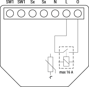
This is Shelly's internal schematic:


Shelly 1L


And this is the no-neutral wiring schematic:


1L without N wiring diagram-20240528-141338.png


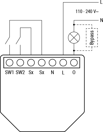
It seems to me that when the internal relay is closed, there will be a 0V potential difference across the L and O terminals. In that case, how does this device remain powered and not simply switch off? Is it magic? 


Create new topic
richms
29098 posts

Uber Geek
+1 received by user: 10209

Trusted
Lifetime subscriber

  #3247425 11-Jun-2024 12:29
Send private message

Are you sure its a relay and not a triac?


Richard rich.ms


sir1963
3428 posts

Uber Geek
+1 received by user: 3756

Subscriber

  #3247429 11-Jun-2024 12:40
Send private message

Nope it will be using a small amount of leakage current through to the load giving it the differential it needs


johno1234

3352 posts

Uber Geek
+1 received by user: 2843


  #3247432 11-Jun-2024 12:51
Send private message

sir1963:


Nope it will be using a small amount of leakage current through to the load giving it the differential it needs


I read similar but still don't understand it. If the relay is closed, and the load is active, the L and O terminals are connected so can't have a potential difference. They are the only two wires going into the Shelly so how is it powered? I think there must be some sort of internal low power load and bypass?


Clearly I am missing something!


If it was a triac as richms mentioned, then there would be the small forward voltage drop, but that would still not be sufficient to power the ESP chip.


johno1234

3352 posts

Uber Geek
+1 received by user: 2843


  #3247433 11-Jun-2024 12:53
Send private message

BTW I've read that the 1L does click loudly when switching so would appear to be a regular mechanical relay not a solid state device.


mkissin
402 posts

Ultimate Geek
+1 received by user: 391

ID Verified
Lifetime subscriber

  #3247434 11-Jun-2024 12:54
Send private message

If you read the specs carefully, there's a 20W minimum load without the neutral. That'll be to guarantee a minimum level of current flow, so they're probably deriving internal power from the voltage drop across a shunt or current transformer type thing.


johno1234

3352 posts

Uber Geek
+1 received by user: 2843


  #3247442 11-Jun-2024 13:21
Send private message

mkissin:


If you read the specs carefully, there's a 20W minimum load without the neutral. That'll be to guarantee a minimum level of current flow, so they're probably deriving internal power from the voltage drop across a shunt or current transformer type thing.


I think I almost understand now.


This guy opened one up - definitely a relay inside:


https://www.youtube.com/watch?app=desktop&v=KyUSPOKIa2s


at 5:24 you can see what does look like a shunt inline with the load (the right hand two pads are L and O terminals)


So it is taking a parasitic voltage drop across an internal shunt when the switch is closed... and therefore needs a minimum current to be flowing hence the bypass requirement for <20W loads.


Thanks!


Create new topic


Geekzone Live »

Try automatic live updates from Geekzone directly in your browser, without refreshing the page, with Geekzone Live now.


Are you subscribed to our RSS feed? You can download the latest headlines and summaries from our stories directly to your computer or smartphone by using a feed reader.