Geekzone: technology news, blogs, forums
Guest
Welcome Guest.
You haven't logged in yet. If you don't have an account you can register now.


KiwiME

217 posts

Master Geek
+1 received by user: 80


#318717 14-Feb-2025 11:17
Send private message quote this post

I need an automatic power transfer (changeover) switch for a rainwater pump on a 20A circuit.  My electrician doesn't seem to be able to come up with anything under $3-4 grand installed, more than twice what I expect is reasonable.


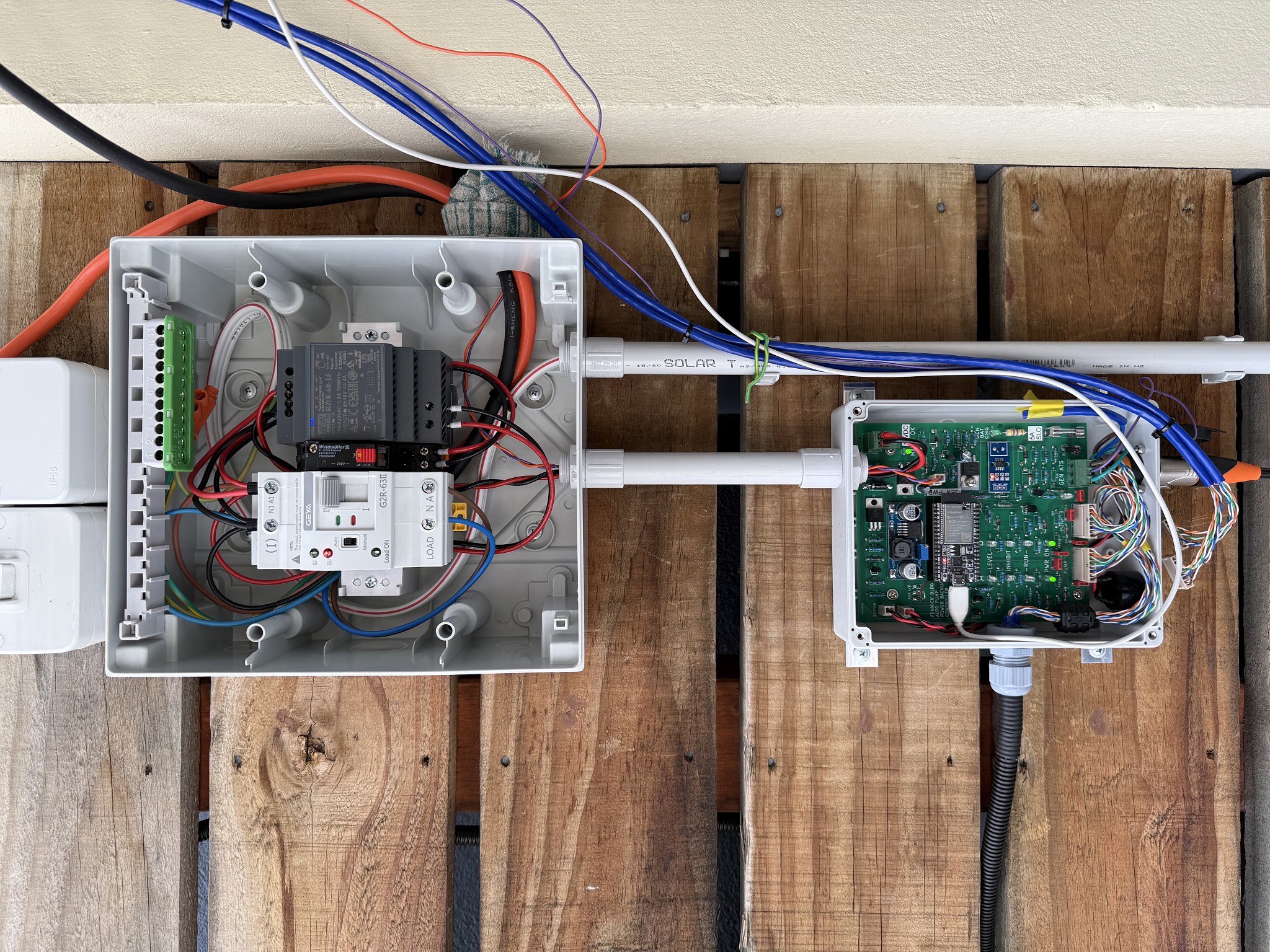
It's literally a changeover contactor and a plastic box placed along the path of an existing circuit with an inlet receptacle for the generator.  When the generator is started it detects that presence and swaps that circuit to the alternative power supply without risking back-feed to the mains.


There is an NZ manufactured one but it's manually-operated. There are a few others with EU certs offered by reputable suppliers priced at $800 to $1500 (for the hardware alone) but it's not clear if those could be signed-off.  There's plenty on eBay that say they comply with EU standards and are attractively priced.


Has anyone had one installed and certified by an electrician in NZ at a reasonable price that could share the source of that part?  I'm in Hawkes Bay.


Create new topic
KiwiME

217 posts

Master Geek
+1 received by user: 80


  #3358759 30-Mar-2025 16:24
Send private message quote this post

After reverse-engineering one great looking prospective transfer switchbox (NZ$800) from reputable company Victronics I realized that all they've done is use a 2-pole double-throw contactor backwards to select the two power sources.  I think that's what my local electrician was proposing as well for a ridiculous $3-4k.  There's no way that's going to be compliant as best as I can see because the flashover isolation between the sources would be inadequate.  Proper changeover switches space the source contacts much further apart and use solenoids or a motor to toggle the load between them.


I eventually purchased a switch that actually complies with IEC 60947.6.1 as required by the NZ 2010 standards and is also quite inexpensive.  It's a compact new design from 2024 and perfectly suits my relatively-light load. But it's also autonomous in operation and has no provision for external low-voltage controls like more expensive ones do.  What I need to do is use the generator to determine when the transfer switches over by placing that as the primary (default) power source rather than the mains.


I can see now why automatic switches don't suit every situation.  You shouldn't just suddenly and blindly suddenly change power to working appliances from one source to another with an unsynchronised phase angle.  Running motors could pull a big spike in current and pop a breaker even if electronics don't care.


So, seeing as my application is for one pump only I've designed a controller that will momentarily disable the pump some tens of seconds before starting the generator.  As soon as the transfer switch sees generator power it will change to that power source irrespective of mains power.  That way if the pump is already running on generator power and the mains suddenly reappears it won't switch back until the generator has been turned off and the pump has stopped.


But there are more challenges once I started looking at installation details.  My existing 6kW conventional 'dumb' petrol generator (only 3 years and still a popular model) has a fully-isolated 230VAC output.  My new 5.5kW conventional (smart 2-wire run) diesel generator has a neutral-chassis bond with an RCD.  It's almost unbelievable that there are two electrical configurations for portable generators on sale today in NZ and neither vendor mentions this significant detail.


The complication resulting is that the electric code seems to require that N from mains to the load is maintained at either transfer switch position to maintain the single established MENs point at the main switchboard. But my diesel generator has its own MENs when grounded and I'm pretty sure but not certain that you can't or shouldn't have both. 


Disconnecting the MEN link in the generator means that the RCD will not work properly if the generator was used in a stand-alone situation.  The obvious answer is for the transfer switch to switch both L and N for the mains source as well as the generator source to allow the load to either MENs without conflict.  


There are many guides on the web from various sources like Worksafe and both NZ and Australian lines companies.  But they cover specific situations such as temporarily running an entire house from a genset in an emergency where you completely disconnect both mains L and N. Further research is needed before I call the electrician.


SirHumphreyAppleby
2950 posts

Uber Geek
+1 received by user: 1882


  #3358761 30-Mar-2025 16:49
Send private message quote this post

I'm not going to pretend I understand the technical details, at least on first glance, but I have been watching this thread and thank you for your update.


Where did you source the GEYA GR2 from and ensure compliance?


KiwiME

217 posts

Master Geek
+1 received by user: 80


  #3358780 30-Mar-2025 17:22
Send private message quote this post

That’s a good question.  I imported this directly from the manufacturer and they have provided copies of the testing and certification documents. Since I’m not selling this item to the public in NZ there is no SCoC. It’s on me and my electrician to accept the compliance. They have other older transfer switch products but this is the first to meet the requirements that NZ has adopted.


KiwiME

217 posts

Master Geek
+1 received by user: 80


  #3400050 4-Aug-2025 22:12
Send private message quote this post

As an update to my thread for anyone interested, over four months later the fully automatic generator backup system for my rainwater pumps is nearly complete. It's now connected between the pumps and their mains supply temporarily using heavy-duty extension cords while I debug the software.  After more testing I'll call my electrician to see if they'll agree to wire it up permanently to the 20A circuit leading to the two pumps that passes by (behind the trellis) where the installation is located on my 1st-floor patio.


It's still based around the automatic low-cost transfer switch ('ATS') that I described above plus a controller PCB that I designed based around an Espressif ESP32 DevkitC microcontroller.  Luckily I have the skills to do the electronics and Arduino-based software adequately but the simple website required a couple of weeks learning some javascript, CSS and websockets - at least well enough to get this working.  Most of the small electronic parts came from Jaycar but others are from the UK, US and China - all with minimal or no shipping costs.  The quality of the circuit board manufacturing, my first time designing such a thing, was especially impressive - and cost only US$60 shipped for the minimum quantity of 5, taking only four days. I just wish I'd made less mistakes...


Aside from managing the generator during power-out and rainfall conditions, it also automatically charges the lead-acid battery in the 6kW generator for 30 minutes twice a day, and tests the two relays that temporarily isolate the two pumps during generator / ATS startup and shutdown. The battery charge is limited to 14.7 V and 2 A.  I also use the current sensor to correct for resistive voltage losses in the wires leading to the generator so that I can accurately know the voltage at the battery terminals.


It's permanently logged into my WiFi and hosts a simple smartphone-sized webpage that indicates the status, much the same as the LEDs on the PCB, but including the live DC supply and battery voltages with charge current, plus I can start a 30-min battery charge if required, or stop one already in progress.  There is also a simple text page hosted that holds timestamped logs of events, alerts and faults.  It's written to non-volatile RAM on the ESP32, so survives loss of power.  'Faults' are also emailed, assuming the WiFi is working when required. 


There's currently no intent to 'control' the generator from the webpage, nor intervene in the automated process.  My logic is that if I can't think of what can happen now while programming this, I won't think of it later under duress.


The basic process is that if the mains power fails the controller will continue to run off the generator battery for 10 minutes in case the power comes back on.  It will then switch itself 'off' to save battery energy.  It only draws about 70 mA so it could run for hours off the 30Ah battery without a problem.


The 300 L rainwater below-ground tank has four new level switches added, two each for redundancy on each of two channels.  If any of the four are are lifted by the water level the controller will boot-up on the gen battery again.  It will then isolate ('inhibit') the pumps (disconnect them from their AC supply using relays) and start the generator.  A relay (to the right of the Geya ATS) indicates to the controller when generator power is present and the transfer switch will automatically change over when it sees that same voltage.   The controller will drop the inhibits in sequence allowing each pump to start separately as to avoid having both start at the same time - should both have been triggered by their own built-in float switches.


It will then time the operation of each pump (noting that normally only one pump runs, the other is a backup) and then decide if it's better to switch off the generator or wait until the tank fills up again.  It will always run the generator long enough to give the battery enough charge to start up again, perhaps 8 minutes.  Note that the higher the rainfall present the longer it takes to pump out the tank, so that's what this decision is based on. 


In very heavy rain a 1-2 minute pumpout might be needed every 6-10 minutes so the generator would stay running during the wait.


If the mains power comes back on during any of this, the process is not disrupted.  The transfer switch is wired to prioritise the generator input, so by controlling when the generator is 'on' or 'off' I can control when the transfer switch changes to the non-priority mains position.  Given that the mains could be flakey when it returns I'd not be in too much of a rush to switch back anyway.


The biggest risk I can think of is if a circuit breaker (or the RCD) trips on the generator.  I'll be able to time-out at the appropriate stage and shut it down, but there's nothing I can do remotely to correct such a fault.  It's critical that I ensure that I minimise the chance of a ground fault or earth leakage due to water ingress in the submerged pumps and their integrated float switches. But I also have to keep the generator from trying to start over and over due to the remaining high water level and no mains power.


Out of about 10 distinct modes of operation I have one which is intended to prevent the system from 'cycling' pointlessly due to an error such as the one above.  If the generator and pump power does not appear when expected after an appropriate time-out I'll move to 'Mode 90' after which it cannot leave without a controller restart.


Here are some photos of the rig. It's had a lot of 'bench' testing but I haven't had it actually start the generator by itself yet.


KiwiME

217 posts

Master Geek
+1 received by user: 80


  #3429012 29-Oct-2025 19:55
Send private message quote this post

Nearly 3 months have passed since my last update and I'm still working full time on this project that I started in February 2025.  The system has actually has been under test for several months but I need it to be compliant to the relevant electrical standard so it can be wired-in permanently, that being A/NZ 3010:2017.


On the software front I was experiencing crashes every few days when the web server was in moderate use, but I think I've resolved it. It wasn't a practical problem because the ESP32 automatically restarts so quickly that it wouldn't cause any operational issues.  But, I hate ignoring what is clearly bad design on my part.


With some pointers from helpful Aussie electricians I've made significant progress on the compliance. It turns out the standard deviates between Oz and NZ regarding the common situation I have, which is that the transfer switch cannot be practically located at the "main switchboard" containing the M-E-N link (where neutral is locally bonded to a dedicated wire leading to the earth electrode).


Instead my transfer switch is 20m away at what's termed a "distribution switchboard" and NZ uniquely requires that it establish a local M-E-N link.  The 'industrial' generator I purchased back in April already has such a link internally (when suitably earth-grounded) but that precise location is not allowed by either NZ or Oz when connected to a transfer switch.


So, first the generator needed the internal M-E-N link removed.  Because it's CE-marked I researched this first and it turns out that both the commonly-found configurations, internally-bonded/RCD-protected and floating outputs comply with the relevant EN standard that is included in the electrical part of the self-declared CE-mark. That was good because I dislike the idea of modifying an agency-approved product, one for which I paid nearly $4k. I still have to do the mod but apparently it will remain EN-compliant.


Based on what I see at the local Mitre10, about 10% of generators on the shelf have an internal bond with RCD protection, those being only the larger conventional types (conventional meaning non-inverter).  None, and I mean exactly none of them indicate this crucial detail in their specifications. The presence (or not) of an RCD is the only clue.


I disassembled the generator's control panel and found exactly what I had expected.  It's made by ITC Power, a reputable Chinese manufacturer, and has a standard of wiring that's not a work of art but good enough. But lifting and insulating the link was very easy as it was clearly marked.


On the plus side, all connections were properly tightened and all used crimped ferrules on the correctly-sized stranded wiring.  I made a schematic drawing of what I found since the NZ vender was unable or unwilling to provide one that was even remotely accurate. Every generator owner should have an accurate electrical schematic. 


Next, I needed to add more switchgear to my panel, requiring that I order a new box 50% larger. As before I purchased an ABB box from RS, shipped from the UK for a very reasonable price.


To meet compliance the incoming mains supply needs an isolator, in practice meaning an MCB (miniature circuit breaker, just a common DIN-mount part). 


The incoming generator power needs an isolator, overcurrent protection and a special 100mA RCD to handle the seemingly-remote risk of "earth potential rise".  According to the standard it's 'optional' but it doesn't explain how you might decide one way or the other.


That latter item was absurdly overpriced locally ($450-1500) so I ordered one from the same vendor as the transfer switch, a bargain at $40 including shipping.


Lastly an RCBO (MCB + RCD) was needed for the output going to the pumps and I sourced that locally.  So, all the parts are in place and it should meet the requirements for compliance.  I need to be sure there are no 'nuisance' RCD trips before I ring the electrician.


I would have mentioned before that I need this system to protect my tenant's property in case there is a power failure during rainfall.  Up to yesterday that's only happened twice in 20 years, but both being within the last 5 years. 


But very early Tuesday the power was out for 2 hours without me knowing and an hour after power was restored it poured down.  I didn't even know until I saw it later in the log file captured by the ESP32.  The generator was not hooked up so I was very lucky. Each pumpout represents about 2mm of rainfall. 1-2 pumpouts missed is enough to cause flooding.


KiwiME

217 posts

Master Geek
+1 received by user: 80


  #3445022 17-Dec-2025 17:31
Send private message quote this post

This will be my last post on this topic as the system has been completed, 'enlivened' and signed-off by my electrician. It all works as designed.


The only last surprise was that I was offered more flexibility as to the mains wiring architecture than I had anticipated based on my interpretation of ANZ 3010-2017.  My electrician would have been happy with the 'Australia-only' method for this situation, where we have a new 'distribution' switchboard located some distance from the 'main' switchboard.


The Aussie arrangement maintains the existing N-GND link established by the main switchboard rather than creating a new one at the new switchboard. Both are similarly-safe but the standard is clear on which should be used in NZ.  A new ground wire was run to the existing electrode. So, when the generator is running the household wiring is totally disconnected.


If I had known about this option and gone the Aussie route (a) it wouldn't be technically compliant and (b) the supplying existing RCBO supplying the circuit could nuisance-trip due to the ATS not switching the neutral. The difference in cost is a wash because the Aussie method would require a fresh 20A circuit.  The NZ method required the above-mentioned ground wire plus the oddball 100mA RCD.


Any questions, just yell.


Shop now on Samsung phones, tablets, TVs and more (affiliate link).
KiwiME

217 posts

Master Geek
+1 received by user: 80


  #3468168 9-Mar-2026 18:54
Send private message quote this post

Being a bit of a perfectionist I've re-spun the PCB after becoming nervous about having 18m of copper wire running from the pump electrical box connecting to (6) of the ESP32 inputs. The ESP32 microcontroller is quite a delicate little flower and is intolerant of any electrostatic discharge or applying electrical signals fractionally outside of the 0-3.3V range.  Of the six I've bought I've already damaged three.  Thankfully they're impossibly inexpensive (US$11), but this particular one, the so-called "dev kit C" is now out of production.


So, I've added optocouplers on all inputs and outputs that extend outside of the enclosure.  For those who don't know, optocouplers are 6-pin ICs that internally have an LED pointing to a phototransistor so that the two sides can pass a digital signal yet be electrically-isolated. The system ground is still in common but any spikes that might be induced on signals should be blocked. 


Additionally I revised the switch-mode buck-converter used for charging the 12V lead-acid generator battery.  I really made a hash of the first version as I didn't know what I was doing. It's way better now and produces smooth DC for the battery to a maximum of 14.6 V and 2A. As before, by continuously measuring the current going to the battery (the little blue PCB) I can compensate for voltage drop in the cable to the generator.


I've improved the accuracy of the voltage readings that appear on the website by about 5 times.  I'm now getting readings reliable to within about 0.02 V instead of 0.10 V. The secret - don't use zener diodes to offset the signal.


Lastly, I've improved the board's automatic swap-over from mains power to generator battery power.  The DC power that goes to the (8) sensors/switches/relays is now better regulated (to 12V) and fused.


I've built-up two of these PCBs because I need one to experiment with software-wise so as not to risk the integrity of the one in service.  Software is at 95%.  It works as required but I would like to add eyeliner and lipstick.  It's amazing how many "corner cases" arise when all you're trying to do is start and stop a generator.  The software now checks the 'precipitation probability' every hour (from open-meteo.com) to determine the urgency of reporting any faults found by email.


Since I started this project January 2025, battery-based bulk AC power has dropped in price and for the same cost as a generator I could now buy an adequate-capacity lithium-iron (LFE) unit. But the controller design can be easily revised to support such a change if that happened in the future.  LFE batteries (think BYD EVs) are considered far safer than NMC (think Hyundai-Kia and most other EVs).  But those power units may not last as long, say 20 years, as an old-fashioned diesel generator.


The website updates every 2 seconds when a web client is connected.  The data in the two lower 'cards' is pushed from the server in JSON format. But it's all "info-only", there's no intent to control the generator remotely.


The generator control algorithm works by staying in defined "modes", any of (11), each dictated by the situation at the time.  The idea is that in each mode you're only concerned with watching what information you need to make a decision to move to another mode.  I got the idea from 'Dungeons and Dragons' type games where you're in one room at a time and have to make a decision solely based only on what you have (in inventory) and what's in front of you. Those decisions would be made the same way as if I was looking at it in person.


Create new topic


Geekzone Live »

Try automatic live updates from Geekzone directly in your browser, without refreshing the page, with Geekzone Live now.


Are you subscribed to our RSS feed? You can download the latest headlines and summaries from our stories directly to your computer or smartphone by using a feed reader.