|
|
|
SomeoneSomewhere: He's got a point. Design is one thing, but you're going to have to convince a sparky to build what you've designed and connect it to 400V.
I thought his point was my choice of terminology had rendered the concept unsafe.
I am not intending to ask a sparky to build anything and even my low voltage devices are off the shelf components. The owner will however be asking his electrical contractor to connect and install those components according to best practices etc. I do not expect he will need to heat his soldering iron and I will only need to heat mine to make necessary connections to the Arduino and maybe not even that as so many modules nowdays ar pluggable.
Perhaps I should recommend the contractor be given the job to build the Arduino circuits too? Who will write the software if I don't? How would they know what to write if I am not permitted to tell them what is required?
Generally flanges work by having the lowest position be straight ahead, and skewing the wheels causes the flange to ride up on the rails.
That is true and exactly the problem, the gantry and wheels get skewed and the gantry wheels climb the rails. But I am not trying to skew the wheels, I will be trying to 'un-skew' them.
Almost every electrician in NZ would not even consider connecting up your "black box" without a suppliers document of conformity (SDoC), all the off the shelf products mentioned in this post have these available, any electrician who installs your "black box" ticks on his certificate of compliance that everything is "electrically safe" and that takes responsibility for the safety of your black box - good luck with that.
That is true and exactly the problem, the gantry and wheels get skewed and the gantry wheels climb the rails. But I am not trying to skew the wheels, I will be trying to 'un-skew' them.
I am suggesting that with no motor and no brakes, gravity may be sufficient to un-skew it. The wheels climb the rails - ergo, the lowest energy position is with the gantry properly sited on the rails. I would try simply disabling the brakes and verifying whether it stops acceptably fast from friction alone, and avoids derailment naturally.
Ah yes, which black box gives you concern (assuming you are confident in telling me)? The Arduino, the tracking sensor, the low voltage power supply or the phase sequence detector?

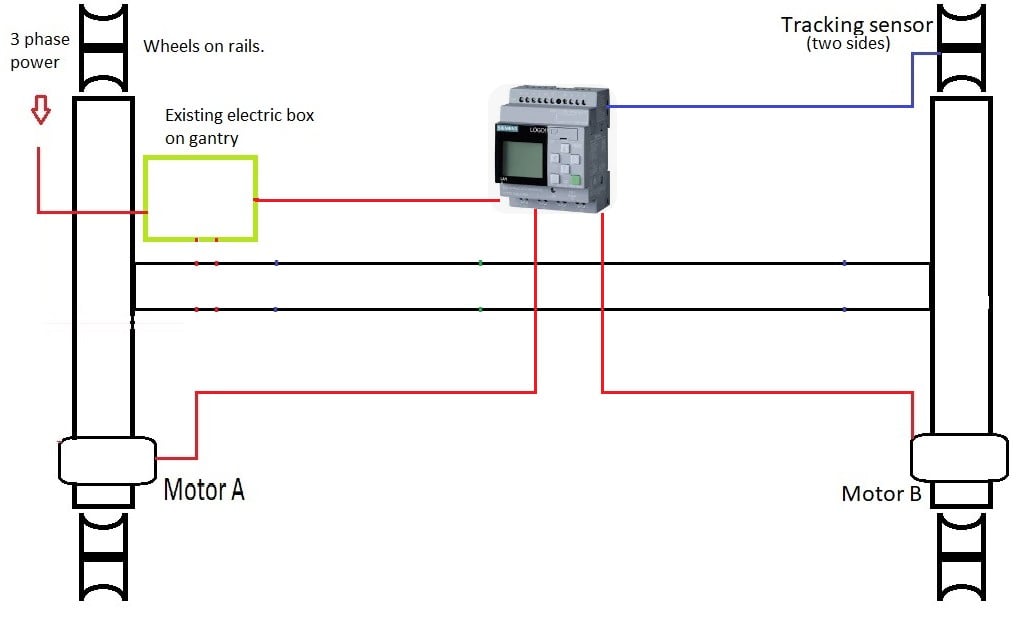
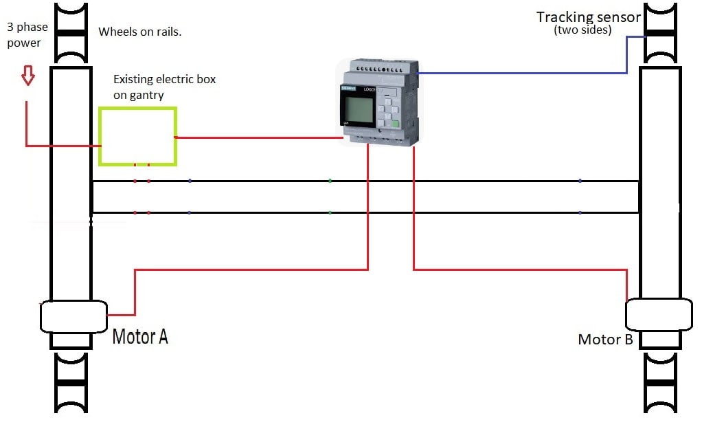
Meanwhile---- I wonder if this is a practical configuration to do the job.
MrJohn:
Ah yes, which black box gives you concern (assuming you are confident in telling me)? The Arduino, the tracking sensor, the low voltage power supply or the phase sequence detector?
Anything that connects to low voltage in NZ requires a SDoC, will your build come with this mandatory document? - I doubt it, next hurdle will be finding an electrician who would be willing to take responsibility without the SDoC
SomeoneSomewhere: I would not want anything pluggable (using pin headers for example) mounted to a moving gantry. Recipe for failure. Also strongly consider using a proper PLC instead of an arduino. Costly but much more rugged. SELV gear doesn't need SDoCs but...
So pluggable is no no and I am not allowed to solder anything....
I am suggesting that with no motor and no brakes, gravity may be sufficient to un-skew it. The wheels climb the rails - ergo, the lowest energy position is with the gantry properly sited on the rails. I would try simply disabling the brakes and verifying whether it stops acceptably fast from friction alone, and avoids derailment naturally.
I am with you now. Unfortunately the rails and wheels have not been designed to take advantage of that. The wheels are actually cylinders of a few inches diameter with disks at each end. My aim is to keep the rails running midway along the cylinder. If I was looking for an angle grinder and welder solution I might be suggesting the wheels be made from two cones, but I would be faced with accommodating doubtless variations in distance between rails.
As it is the wheels are effectively braked as they are chain drive from a worm reduction gearbox which will not back-drive (easily).
Meanwhile:- is this a practical scheme and would it meet universal approval on this forum?

What other components might be required?
sorry this is not quite my field but i know of a few similar things.
one of the common setups is to use a distance sensor (lazer etc) to feedback on a VSD. typically have them on pumps to maintain a set level in a tank. tank goes down, pump slows down. i suspect something similar may work in your set up, wheels move off track motor slows down/speeds up. that uses off the shelf parts and setup, industry lego, so no sparky issues.
hope that helps.
tweake:
sorry this is not quite my field but i know of a few similar things.
one of the common setups is to use a distance sensor (lazer etc) to feedback on a VSD. typically have them on pumps to maintain a set level in a tank. tank goes down, pump slows down. i suspect something similar may work in your set up, wheels move off track motor slows down/speeds up. that uses off the shelf parts and setup, industry lego, so no sparky issues.
hope that helps.
OK, thanks. However I think I have been told here that industrial Lego is a no-no without the approval of the guy with his clip-board.
MrJohn:
tweake:
sorry this is not quite my field but i know of a few similar things.
one of the common setups is to use a distance sensor (lazer etc) to feedback on a VSD. typically have them on pumps to maintain a set level in a tank. tank goes down, pump slows down. i suspect something similar may work in your set up, wheels move off track motor slows down/speeds up. that uses off the shelf parts and setup, industry lego, so no sparky issues.
hope that helps.
OK, thanks. However I think I have been told here that industrial Lego is a no-no without the approval of the guy with his clip-board.
not that i'm aware of. its standard, off the shelf, pre approved products.
tweake:
not that i'm aware of. its standard, off the shelf, pre approved products.
OK, thanks. But it seems that electrical devices including Arduino (5V) and the attached sensors require an SDoC for installation in the manner I was contemplating. There is even some problems with me drawing a layout of what I want for the electrical contractor to install.
So really, even pre approved devices requiring a fixed installation are out of scope for me.
MrJohn:
tweake:
not that i'm aware of. its standard, off the shelf, pre approved products.
OK, thanks. But it seems that electrical devices including Arduino (5V) and the attached sensors require an SDoC for installation in the manner I was contemplating. There is even some problems with me drawing a layout of what I want for the electrical contractor to install.
So really, even pre approved devices requiring a fixed installation are out of scope for me.
i think the guys are being a bit picky. tho i understand the concern with custom made HV gear.
custom HV gear needs tick from sparky as per any HV install and that will depend on the sparky. low voltage such as sensors no such requirements. ie if sparky installs VSD, you can wire any low voltage control circuit to your hearts content.
I have skimmed through this but don't remember any mention of how the mis-alignment is being measured.The purpose of all this is to prevent it going too far so how is it being measured. This surely is the key and will be needed as it is the basis of any solution.
|
|
|
