Geekzone: technology news, blogs, forums
Guest
Welcome Guest.
You haven't logged in yet. If you don't have an account you can register now.


datahawk

251 posts

Ultimate Geek

Lifetime subscriber

#293994 26-Feb-2022 17:22
Send private message

I suspect that there are a few Mitsubishi installers/technicians floating around on this forum so I'm hoping that someone will have some helpful info on options to repair one of our outdoor units...


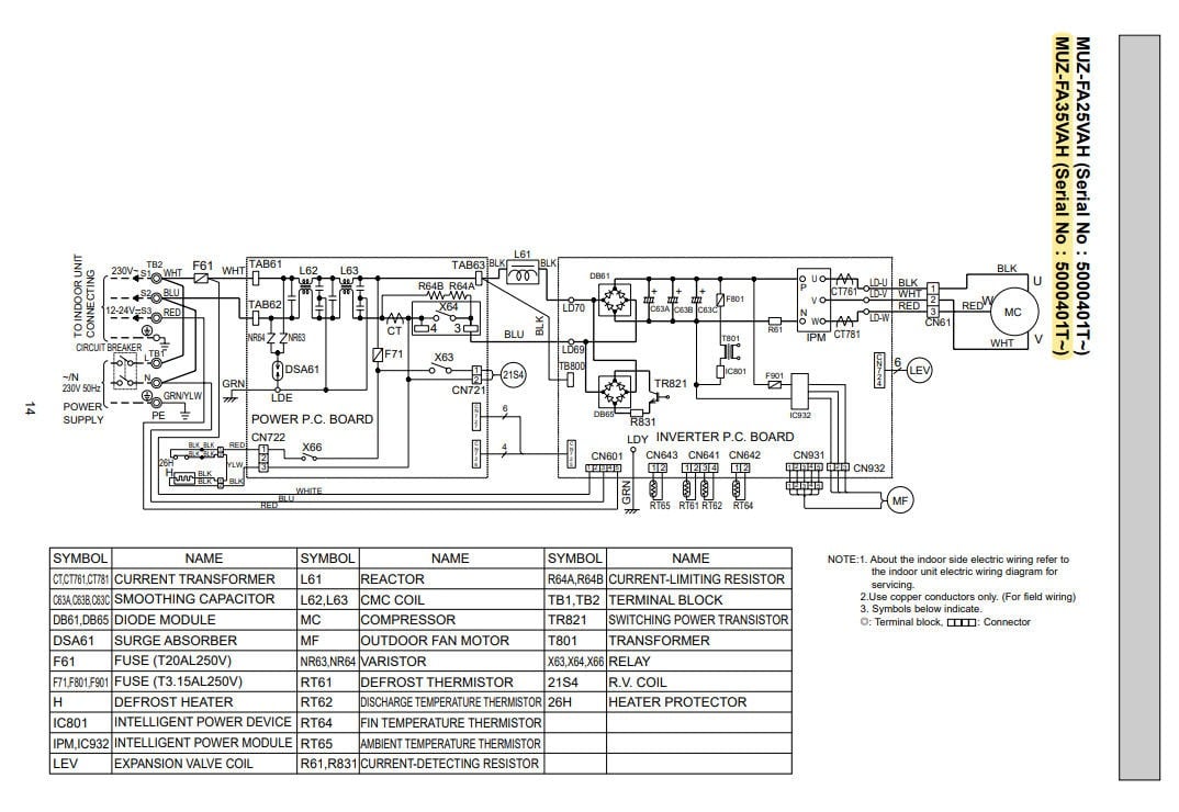
I have a (now obsolete) MUZ-FA35VA outdoor unit reporting an inverter over current fault - Diagnostic codes are: 5 x sequence power LED flash in the indoor unit with a 2 x sequence flash on the red inverter LED. The inverter compressor will not start. 


The outdoor fan does attempt to start every 3-5 minutes until the indoor unit stops operating and drops into fault mode.


This PCB is obsolete and not available from the factory but my electronics hobby 'fix-it' mentality tells me it should be repairable if I can find an expert tech that can locate the actual over current fault?


I am an electronics enthusiast so I understand the basic circuits and I have extensively tested the power PCB and inverter PCB in place and also powered up on my lab bench (with the reactor connected) but I cannot locate the actual faulty component.


(a) The compressor winding resistances test fine with no ground shorts.


(b) RV Coil, LEV Coil, Fan Motor, and all Thermistors are within test ohm range.


(c) 230V AC is being rectified correctly to approximately 320V DC across test points on the inverter board and expected DC voltages are routing to the IPM module correctly.


(d) The Reactor tests fine with no shorts.


(e) Testing of the live board shows correct high 300V+ DC voltages and regulated low DC voltages (e.g 13V, 5V, 12V) are arriving to all expected destination points.


(f) Diode mode tests of the IPM module (in-place) are all correct with no shorts or invalid values across the W-V-U inputs/outputs or to ground. When bench tested and powered on the expected stable 15V DC can be measured on the IPM W-V-U output.


However when the PCB is installed in the outdoor unit and indoor powered up there is no AC voltage generated on the compressor output as the inverter has dropped into the over current fault.


If anyone can recommend an electronics expert willing to have a crack at trying to fix this type of inverter board, please let me know.


Filter this topic showing only the reply marked as answer Create new topic
dasimpsonsrule
147 posts

Master Geek


  #2875427 26-Feb-2022 18:36
Send private message

Do you have a scope to measure the voltage output to the compressor when it tries to start? It's possible the compressor is stalled which I think gives the same overcurrent error.


datahawk

251 posts

Ultimate Geek

Lifetime subscriber

  #2875432 26-Feb-2022 18:56
Send private message

Thanks for the suggestion - I have a Service Manual for this outdoor unit along with the test procedures.


The main test for the inverter output is to disconnect the compressor lead, start the indoor in emergency mode and test for at least 50V AC across the three output U-V-W terminals.


I've checked this numerous times and there is no AC voltage being generated by the IPM so I highly doubt that it is a compressor stall.


It appears that the inverter drops into fault mode as soon as the indoor is started.


  #2875513 26-Feb-2022 20:35
Send private message

Does it have current shunts or CTs to measure the output current? I would inspect those and associated circuitry.


dasimpsonsrule
147 posts

Master Geek


  #2875519 26-Feb-2022 20:42
Send private message

datahawk:


Thanks for the suggestion - I have a Service Manual for this outdoor unit along with the test procedures.


The main test for the inverter output is to disconnect the compressor lead, start the indoor in emergency mode and test for at least 50V AC across the three output U-V-W terminals.


I've checked this numerous times and there is no AC voltage being generated by the IPM so I highly doubt that it is a compressor stall.


It appears that the inverter drops into fault mode as soon as the indoor is started.


OK, I had a look at the service manual too. Looks like there are 2 current shunt resistors, R61 and R831. R831 is part of the AC-DC conversion circuit so I think that is probably OK. Does R61 look OK?


datahawk

251 posts

Ultimate Geek

Lifetime subscriber

  #2875533 26-Feb-2022 21:20
Send private message

dasimpsonsrule:


OK, I had a look at the service manual too. Looks like there are 2 current shunt resistors, R61 and R831. R831 is part of the AC-DC conversion circuit so I think that is probably OK. Does R61 look OK?


Great, Thanks.  Yep - R61 and R831 both seem good and read 0.1 ohm on my meters.


There is also IC801 - Intelligent Power Device (Panasonic MIP0223SY) - that I wonder about as it's outside my skill range to confirm if it is operating correctly...


It seems to be working and providing high voltage to the ZD801 transient diode/rectifier through to the T801 transformer that is powering the low voltage circuits but if I could source another to try I would do so. However, I can only find them on E-Bay.


I will isolate the board and my scope tomorrow and get some better readings from that IC. Initial tests showed a 300V+ high voltage with an AC waveform feeding the ZD801.


Thanks for looking.


datahawk

251 posts

Ultimate Geek

Lifetime subscriber

  #2875536 26-Feb-2022 21:29
Send private message

SomeoneSomewhere:


Does it have current shunts or CTs to measure the output current? I would inspect those and associated circuitry.


Yes there are two CT's in the circuit. I admit that I have not tested these directly. Maybe I should have probe around tomorrow :)


dasimpsonsrule
147 posts

Master Geek


  #2875561 26-Feb-2022 22:54
Send private message

datahawk:


Great, Thanks.  Yep - R61 and R831 both seem good and read 0.1 ohm on my meters.


There is also IC801 - Intelligent Power Device (Panasonic MIP0223SY) - that I wonder about as it's outside my skill range to confirm if it is operating correctly...


It seems to be working and providing high voltage to the ZD801 transient diode/rectifier through to the T801 transformer that is powering the low voltage circuits but if I could source another to try I would do so. However, I can only find them on E-Bay.


I will isolate the board and my scope tomorrow and get some better readings from that IC. Initial tests showed a 300V+ high voltage with an AC waveform feeding the ZD801.


Thanks for looking.


I'd say if you have low voltages OK then IC801 is working, looks to be a switchmode all in one type chip


Move to New Zealand's best fibre broadband service (affiliate link). Free setup code: R587125ERQ6VE. Note that to use Quic Broadband you must be comfortable with configuring your own router.
datahawk

251 posts

Ultimate Geek

Lifetime subscriber

  #2875842 27-Feb-2022 18:29
Send private message

I've spent another day probing around this inverter PCB with my scope.


The two Current Transformers test out OK and they both feed into a standard dual LM358 comparator.


The LM358 input and output voltages are all present and it does not appear to be defective. I guess that the LM358 would deliver a shutdown high/low signal to the micro controller should the AC output current to the compressor exceed its limits - however, in this case, the compressor is not getting any AC current from the IPM even at initial power up because the AC is not being generated.


I also removed a large Toshiba GT30J322 IGBT that is in the circuit and fed by the secondary rectifier under the heat sink. It is a large chip that tested out OK and I even set up a 12V battery and light bulb circuit test to check that it is switching correctly.


A frustrating problem because I can't pinpoint the cause of the fault. It's possible that the IPM is faulty even though it tests fine but I can't find a match online for this particular module.


I would love to get my hands on a working inverter board but they are rare now. There are probably dozens of these older MUZ units thrown into junk yards - Anyone know where the junk goes to die?


If any of you Mitsubishi Technicians have any of these old PCB's (or old MUZ-FA25/35VA or MUZ-GA35VA outdoor units) in your workshops, I'll be very keen to lay my hands on them.


insane
3240 posts

Uber Geek

ID Verified
Trusted

  #2875870 27-Feb-2022 20:44
Send private message

Could you be getting no AC to the compressor as you don't have a load on the circuit?

Do you have another power source you can use the energise it to confirm its not fried?

datahawk

251 posts

Ultimate Geek

Lifetime subscriber

  #2875873 27-Feb-2022 21:12
Send private message

insane: Could you be getting no AC to the compressor as you don't have a load on the circuit?

Do you have another power source you can use the energise it to confirm its not fried?


Thanks for the response - The inverter does not require a load. There are test procedures that require disconnecting the compressor to test that the inverter board is operating correctly by measuring the AC output - This is our problem - There is no AC output from the inverter PCB due to a fault somewhere.


As I understand it from several hours of research - You cannot hook up any other utility type power source directly to a DC Inverter compressor. It must be driven by an inverter circuit that uses IGBT and/or IPM (Intelligent Power Module) devices.


I do wonder, and will be asking a few installers, if they do have a special test utility device for the purpose of powering up inverter compressors?


dasimpsonsrule
147 posts

Master Geek


  #2875909 27-Feb-2022 22:43
Send private message

datahawk:


I've spent another day probing around this inverter PCB with my scope.


The two Current Transformers test out OK and they both feed into a standard dual LM358 comparator.


The LM358 input and output voltages are all present and it does not appear to be defective. I guess that the LM358 would deliver a shutdown high/low signal to the micro controller should the AC output current to the compressor exceed its limits - however, in this case, the compressor is not getting any AC current from the IPM even at initial power up because the AC is not being generated.


I also removed a large Toshiba GT30J322 IGBT that is in the circuit and fed by the secondary rectifier under the heat sink. It is a large chip that tested out OK and I even set up a 12V battery and light bulb circuit test to check that it is switching correctly.


A frustrating problem because I can't pinpoint the cause of the fault. It's possible that the IPM is faulty even though it tests fine but I can't find a match online for this particular module.


I would love to get my hands on a working inverter board but they are rare now. There are probably dozens of these older MUZ units thrown into junk yards - Anyone know where the junk goes to die?


If any of you Mitsubishi Technicians have any of these old PCB's (or old MUZ-FA25/35VA or MUZ-GA35VA outdoor units) in your workshops, I'll be very keen to lay my hands on them.


Searching for the PS21244 which is the first few letters of the IPM module finds some results, a few datasheets and a replacement on ebay. Might be able to use that info to further test, or spend a few bucks and grab a replacement and hope for the best.


datahawk

251 posts

Ultimate Geek

Lifetime subscriber

  #2875917 27-Feb-2022 23:11
Send private message

dasimpsonsrule:


Searching for the PS21244...


Ha! - I wondered where you got that part number from until I took another look at what I thought was just a vent slot under IPM!


Talk about 'not seeing the wood for all the trees' - I did not notice the numbers were there until I put a torch beam into the slot.


Many thanks - spent time looking at images today to try and identify what is was as I did not want to try 'cooking' the IPM off the PCB yet.


Cheers.


Edit: Duh - And I see it's listed in the service manual - I need to read things slower :)


datahawk

251 posts

Ultimate Geek

Lifetime subscriber

  #2876416 28-Feb-2022 18:21
Send private message

F.Y.I - The fault on the inverter board has been found thanks to this quick reply from modulerepair.com.au


I sent a message with symptoms and test data and asked if they could have a look and send me an invoice. I received this: 'Common problem with that board is corrosion eats though a smaller track leaving it open circuit.'


My initial thoughts were no, this board is in good condition and that won't be the problem but after testing the small tracks feeding the IPM, there was one track with resistance where is should not be. Bypassed that track with a jumper and installed the board into the outdoor unit...


The compressor started running after a couple of minutes. A simple fix if you know what to look for!


However, a few minutes later two 5W current limiting resistors R64A and R64B cooked themselves on the AC power board! - Could be something I have damaged handling the board many times but progress has been made.


dasimpsonsrule
147 posts

Master Geek


  #2876564 28-Feb-2022 20:44
Send private message

datahawk:


F.Y.I - The fault on the inverter board has been found thanks to this quick reply from modulerepair.com.au


I sent a message with symptoms and test data and asked if they could have a look and send me an invoice. I received this: 'Common problem with that board is corrosion eats though a smaller track leaving it open circuit.'


My initial thoughts were no, this board is in good condition and that won't be the problem but after testing the small tracks feeding the IPM, there was one track with resistance where is should not be. Bypassed that track with a jumper and installed the board into the outdoor unit...


The compressor started running after a couple of minutes. A simple fix if you know what to look for!


However, a few minutes later two 5W current limiting resistors R64A and R64B cooked themselves on the AC power board! - Could be something I have damaged handling the board many times but progress has been made.


Good result kinda! I wonder if that relay that bypasses the resistors is bad. Most switchmode supplies those resistors are only in circuit for a few seconds so the caps charge without the huge inrush. 


datahawk

251 posts

Ultimate Geek

Lifetime subscriber

  #2876577 28-Feb-2022 21:26
Send private message

dasimpsonsrule:


Good result kinda! I wonder if that relay that bypasses the resistors is bad. Most switchmode supplies those resistors are only in circuit for a few seconds so the caps charge without the huge inrush. 


It might have been all my fault - I had left a lot of liquid flux residue over the bridge rectifier terminals while removing and replacing the big IGBT to test it yesterday and in my haste to try the track repair I installed the board without noticing the goo. It's possible that this flux was conducting at high current.


I'll know for sure when I can find some 5W resistors to replace them :)


Filter this topic showing only the reply marked as answer Create new topic


News and reviews »

Air New Zealand Starts AI adoption with OpenAI
Posted 24-Jul-2025 16:00


eero Pro 7 Review
Posted 23-Jul-2025 12:07


BeeStation Plus Review
Posted 21-Jul-2025 14:21


eero Unveils New Wi-Fi 7 Products in New Zealand
Posted 21-Jul-2025 00:01


WiZ Introduces HDMI Sync Box and other Light Devices
Posted 20-Jul-2025 17:32


RedShield Enhances DDoS and Bot Attack Protection
Posted 20-Jul-2025 17:26


Seagate Ships 30TB Drives
Posted 17-Jul-2025 11:24


Oclean AirPump A10 Water Flosser Review
Posted 13-Jul-2025 11:05


Samsung Galaxy Z Fold7: Raising the Bar for Smartphones
Posted 10-Jul-2025 02:01


Samsung Galaxy Z Flip7 Brings New Edge-To-Edge FlexWindow
Posted 10-Jul-2025 02:01


Epson Launches New AM-C550Z WorkForce Enterprise printer
Posted 9-Jul-2025 18:22


Samsung Releases Smart Monitor M9
Posted 9-Jul-2025 17:46


Nearly Half of Older Kiwis Still Write their Passwords on Paper
Posted 9-Jul-2025 08:42


D-Link 4G+ Cat6 Wi-Fi 6 DWR-933M Mobile Hotspot Review
Posted 1-Jul-2025 11:34


Oppo A5 Series Launches With New Levels of Durability
Posted 30-Jun-2025 10:15


Geekzone Live »

Try automatic live updates from Geekzone directly in your browser, without refreshing the page, with Geekzone Live now.


Are you subscribed to our RSS feed? You can download the latest headlines and summaries from our stories directly to your computer or smartphone by using a feed reader.