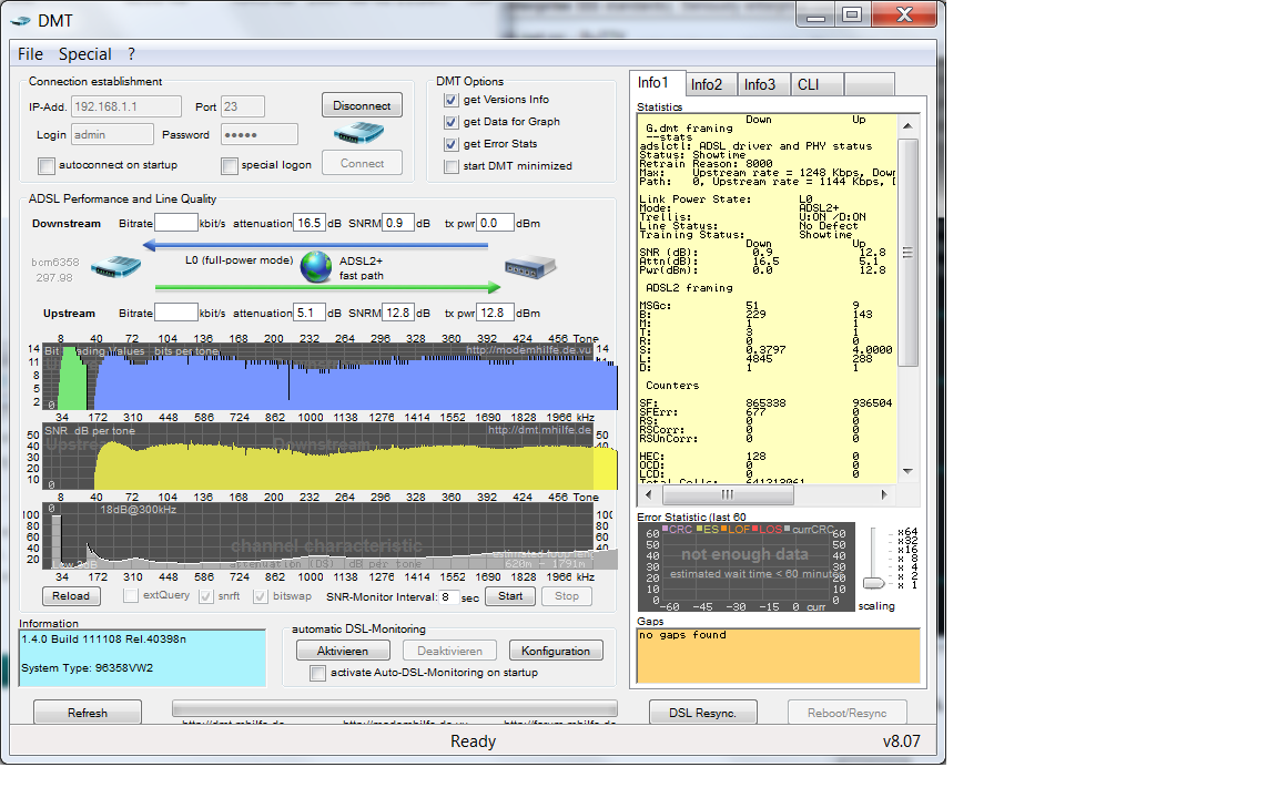
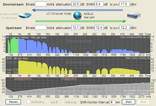
Below is a graph of the bits per bin and SNR for each of the bins in the frequency spectrum used by ADSL2+. There are clearly some chunks of the spectrum that aren't even being used, which probably accounts for our low sync rate of 7.2Mbit with 6dB noise margin or 5.5Mbit with 12dB noise margin.

Below is a screenshot with an overlay showing what it should look like for a good line. The rectangle would be for a perfect line. The sloped shape is perhaps more like what it should look like when accounting for attenuation.

Is there anyone in the geekzone area that knows how to interpret these DMT graphs?
I've done a lot of searching on the internet but not found much concrete information. Generally it seems that some of the frequencies can be knocked out of use by noise interference external to the line or by noise caused by network topology, e.g. things like bridge taps.
The attenuation for the higher frequency bins does get high but some of those frequencies still manage to be used for transmitting data even when bins next to them don't even though the attenuation is similar.
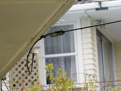
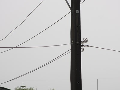
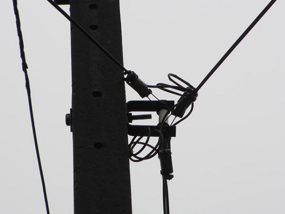
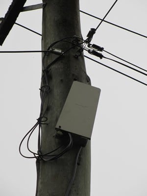
Our house setup:
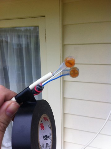
Line comes off pole and into house via plastic POE on fascia of house.
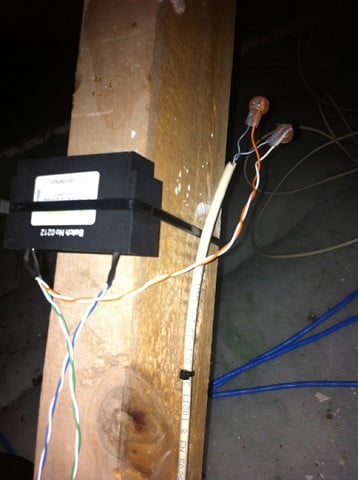
In the roof the line connects directly to a Dynamix VDSL capable master filter (soldered to orange pair on filter as the incoming black phone line was too thick to use a scotch lock).
Filter connects to Hubble phone module (blue pair to blue lines, green pair to green lines)
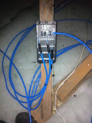
2 cat6 phone lines connect to the Hubble phone module using blue lines.
1 cat6 line connects to the Hubble phone module using a green line and goes straight to an RJ45 jack point near modem.
Custom made RJ45 to RJ11 lead goes to ADSL2+ modem (Netgear DGN2200)
POTS alarm has an RX11 connection to the Hubble phone module, again via cat6.
The modem connects at the same speed the Chorus tech connected when using the line directly off the pole. That's the only testing Chorus have done to date.