I ended up replacing some of the interconnecting wires with thicker copper wire. This seems to have greatly reduced the issue. I've only observed one random glitch in 1.5 days (not watching constantly), but it's not repeatable like it was previously. Hopefully replacing a bit more of the wiring (for the solenoid and relays) will completely eliminate the issue.
Looks like you are getting a voltage dip. Probably not surprising given the wiring length.
Maybe a couple of high value electrolytic capacitors across the 12v supply as it enters your controller panel.
4700uF or better @25v. Would eliminate the need to replace the 12v supply cable.
I was holding off replying until I had a chance to get more pictures.
The main supply is 10mm^2. This is only used for the underground connection. From there the electronics (as seen in the picture) is connected via 16 AWG cable, and the pump has a direct 12 AWG connection.
Other than installing diodes, the only change has been to replace some of the cheap white cable with 0.75mm^2 copper stranded cable. The white cable wasn't as thick as I thought, and only rated to 1A. This is too thin for the solenoid (although the duty cycle is very low), but given the issues were occurring even when the coil wasn't energised, that alone didn't explained the problem. I suspected there was a dodgy connection in there somewhere and I'm hopeful the better quality cable has sorted that.
I can hear the fan speed change when the solenoid kicks in, so there probably is still a voltage drop, but not enough to cause a reset anymore.
Sorry for the delay. I can't get my phone to work with FreeBSD so I need to use a VM to get images off it.
These should give you a good idea of how it's all setup.
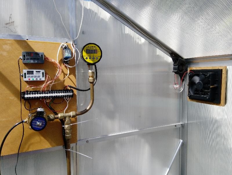
Overview of electronics and active cooling. The parts are as per my earlier post. When the fans power on, the DPDT relay is switched, reversing the polarity to the linear actuator, opening the window. The blower fan helps keep the electronics cool and directs air towards the open window at the top of the greenhouse. The larger fan is an exhaust fan to removed hot air.
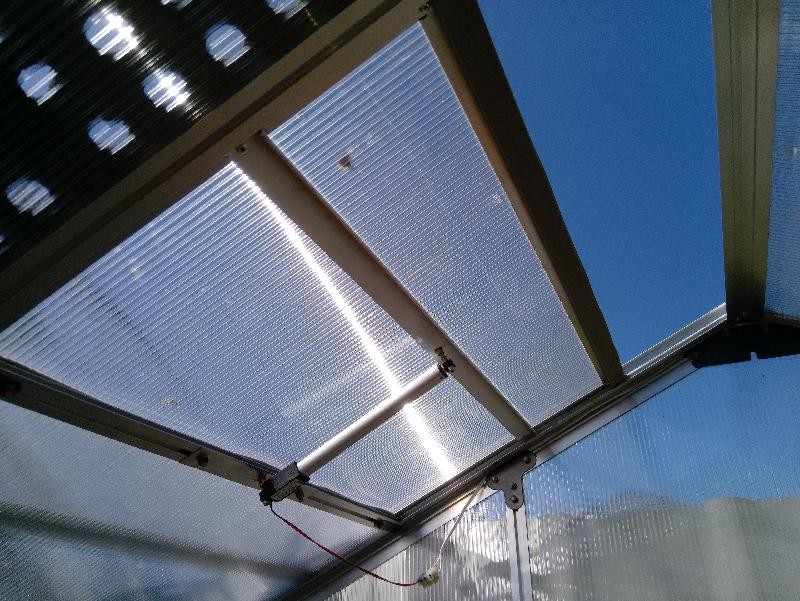
The window has been modified to slide up and down on some spare LED lighting extrusions I had in the garage, stuck on with JB Weld. The original plan was to tilt the window (which gave a much bigger opening), but the window is designed to slot into an extrusion rather than having proper hinges. This resulted in horizontal movement when the window was moving, leading to it getting caught on the frame. In hindsight, adding new hinges would probably have been a better choice, but I used what I had.
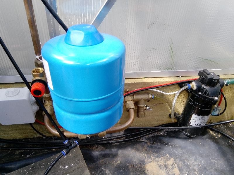
From left to right. Power coming from underground, pressure relief valve, pressure tank, ball valve to drain the system, a 160psi pump and relay to switch it on/off. The pressure switch on the pump is bypassed, and the system is kept at 80-100psi using the pressure switch on the electronics panel. Ideally the pressure switch should be near the tank, but you will also note the very small 6mm hose uses to connect the plant boxes (not pictured, sorry I forgot get photos of those, but they are 100L plastic containers with two 0.4mm nozzles each), so the 'tap' (solenoid) is nowhere near the outlet. This is far enough away to not cause unnecessary cycling of the pump. The clear hose will be replaced with black (UV resistant) and a check valve when that finally arrives.
Looks like you've put "bootlaces" (ferrules) on some or most of the cables. Hard to tell but have you used those on all the cables that are going into the terminal block?
Looks like you've put "bootlaces" (ferrules) on some or most of the cables. Hard to tell but have you used those on all the cables that are going into the terminal block?
It's a bit of a mixed bag. I used them on the 0.5mm cable initially as they were a perfect fit for the screw terminals on the control units. The 0.75mm ferules won't fit in those so I didn't use them for the replacement cables. Where I do use them, if there is more than one wire in the terminal, they both have ferrules to ensure even pressure across the terminal.
Are you subscribed to our RSS feed? You can download the latest headlines and summaries from our stories directly
to your computer or smartphone by using a feed reader.