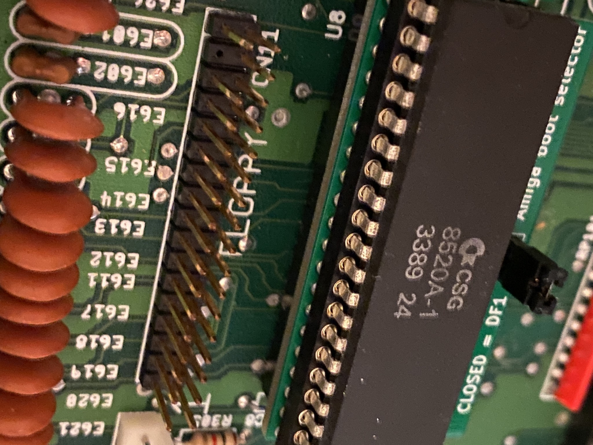
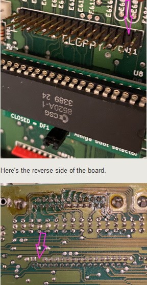
I've been enjoying retro computing the last few months, upgrading my Amiga 500 with new features (RGB2HDMI, a GoEx floppy drive emulator) but the latest project has caused some damage. I was installing a switching socket that would let me switch between the original internal floppy drive and the new GoEx drive (installed as an external floppy drive) for booting, but the 34-pin floppy header on the motherboard got damaged, and one of the critical pins broke off/came out.
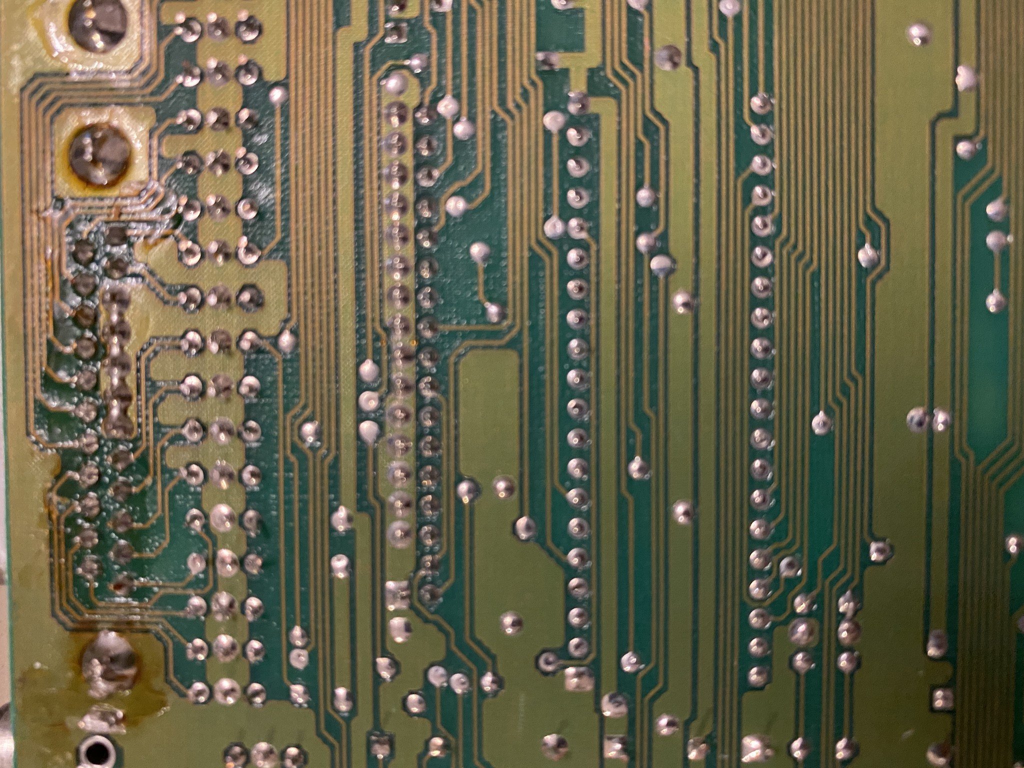
As far as I can tell, the only real solution is to desolder the old floppy pin header and solder in a new header. However, this is beyond my usual skill level with a soldering iron. I'm hoping to draw on support from my local makerspace, but I wanted to check with others that may have experience in modding/soldering with older computers. Is there a practical alternative to what I've outlined?