Geekzone: technology news, blogs, forums
Guest
Welcome Guest.
You haven't logged in yet. If you don't have an account you can register now.


SpookyAwol

626 posts

Ultimate Geek


#305789 4-Jun-2023 09:39
Send private message

Any electrical experts can confirm these are for the same purpose?

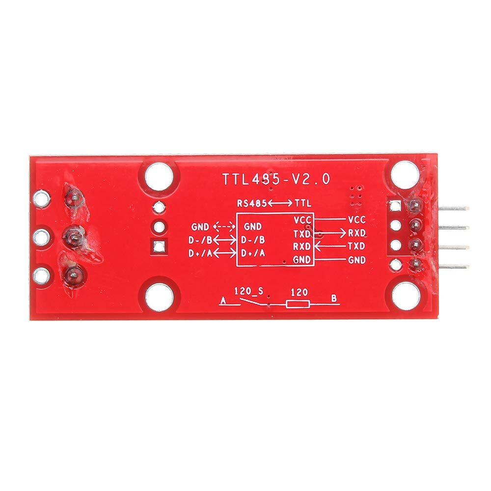
The bottom module (red) works for a MODBUS interface, but interested in using the top one (blue) if suitable due to smaller form factor


Max3485 Module Ttl To Rs485 Usart Communication Accessories Serial Parallel  Multi-machine Communication - Buy Max3485 Module,Ttl To ...


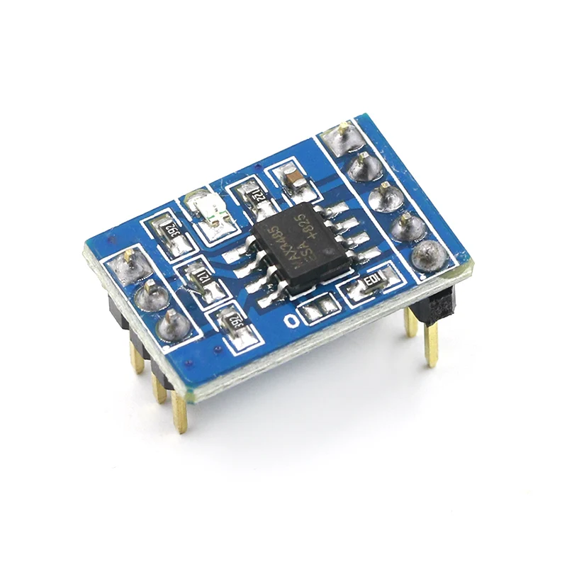
MAX3485 module TTL to RS485 Usart communication


DollaTek MAX3485 TTL to RS485 Module MCU Development Converter Module Card  Accessories Removable Replacement


MAX3485 Module TTL To RS485 Module MCU


Using the same pinouts doesnt work and the top one has an additional pin I cant find documented "EN" - well not that I can find anything on this module
When I say doesnt work, I get a TX but no RX response
Ive tried swapping RX/TX and also A/B
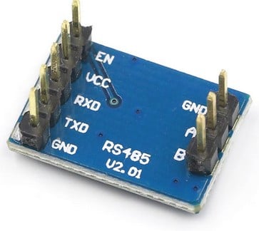

Create new topic
dasimpsonsrule
147 posts

Master Geek


  #3084586 4-Jun-2023 10:07
Send private message

On an RS485 bus only 1 device can transmit at a time, so the enable pin is needed to enable the driver driving the bus, and it must be disabled after transmitting otherwise no other device can transmit on the bus. The RS485 driver chips usually have 2 enable inputs, one which enables the transmitter, and one which enables the receiver. These are usually setup in the opposite polarity, so that if they are wired together then the driver can be used as a receiver or and transmitter by the state of the pin. The other option is to pull the receive enable to ground and have the receiver enabled all the time, the disadvantage to this is that the receiver will receive what is being transmitted. On your module at the top, they are probably tied together. The red board has a lot more components, they are probably using a resistor network to produce a 1 on the RS485 bus, and then enabling the transmitter to produce a 0 on the bus. This is not as reliable as the proper driving of the enable signal, but it works if you have only a few devices, with a slow baud rate, and a short cable


  #3084592 4-Jun-2023 10:13
Send private message

Per the datasheet (p7), pin 2 is:


Receiver Output Enable. RO is enabled when RE is low; RO is high impedance when RE is high. If RE is high and DE is low, the device will enter a low-power shutdown mode.


So tie EN to ground. 


Both of these are little more than a breakout for the IC with some passive components - the red ones also have termination resistors, but that's probably only necessary on longer cables. Possible more ESD/surge, protection too.


If space is a premium, designing the actual IC onto your own PCB along with other components is probably going to give you a much smaller form factor.


SpookyAwol

626 posts

Ultimate Geek


  #3084657 4-Jun-2023 11:15
Send private message

I guess thats why the slight confusion, some use RO RE etc, others RX, TX etc


RO RE version
It seems when using this, RE and DE are tied together and linked to D5 on a Wemos ESp8266

RS485-TTL Module [4519] : Sunrom Electronics

Below is my version which doesnt use D5 and only RXD and TXD to pins D6 and D7
Still using ground, 3.3v of course
Buy MAX3485 TTL TO RS485 CONVERTER MODULE | iFuture Technology
I think I did try EN to ground, but Ill try again 


SpookyAwol

626 posts

Ultimate Geek


  #3084707 4-Jun-2023 11:52
Send private message

This is what Im using for the red MAX3485 (And works well)
WiringDiagramMAX3485

As opposed to a MAX485:

WiringDiagramMAX485

I assume the blue module is more aligned with the 3485 than the 485 (exactly the same pins and naming), but has the inclusion of the extra EN pin


neb

neb
11294 posts

Uber Geek

Trusted
Lifetime subscriber

  #3084717 4-Jun-2023 13:07
Send private message

Man, I know this place is called Geekzone, but I still didn't expect that many experts on obscure data bus hardware...

SpookyAwol

626 posts

Ultimate Geek


  #3084769 4-Jun-2023 14:45
Send private message

neb: Man, I know this place is called Geekzone, but I still didn't expect that many experts on obscure data bus hardware...
😂

Can only hope ;)


  #3084780 4-Jun-2023 15:47
Send private message

I'm pretty sure both the parts you linked are based on the MAX3485, not the MAX485. So you should be able to just trace pads on the one that works and compare with the other one to see what the difference is. 


Not really familiar with 485 behind the scenes, but there's a lot of stuff built on it.


Create new topic


News and reviews »

Air New Zealand Starts AI adoption with OpenAI
Posted 24-Jul-2025 16:00


eero Pro 7 Review
Posted 23-Jul-2025 12:07


BeeStation Plus Review
Posted 21-Jul-2025 14:21


eero Unveils New Wi-Fi 7 Products in New Zealand
Posted 21-Jul-2025 00:01


WiZ Introduces HDMI Sync Box and other Light Devices
Posted 20-Jul-2025 17:32


RedShield Enhances DDoS and Bot Attack Protection
Posted 20-Jul-2025 17:26


Seagate Ships 30TB Drives
Posted 17-Jul-2025 11:24


Oclean AirPump A10 Water Flosser Review
Posted 13-Jul-2025 11:05


Samsung Galaxy Z Fold7: Raising the Bar for Smartphones
Posted 10-Jul-2025 02:01


Samsung Galaxy Z Flip7 Brings New Edge-To-Edge FlexWindow
Posted 10-Jul-2025 02:01


Epson Launches New AM-C550Z WorkForce Enterprise printer
Posted 9-Jul-2025 18:22


Samsung Releases Smart Monitor M9
Posted 9-Jul-2025 17:46


Nearly Half of Older Kiwis Still Write their Passwords on Paper
Posted 9-Jul-2025 08:42


D-Link 4G+ Cat6 Wi-Fi 6 DWR-933M Mobile Hotspot Review
Posted 1-Jul-2025 11:34


Oppo A5 Series Launches With New Levels of Durability
Posted 30-Jun-2025 10:15


Geekzone Live »

Try automatic live updates from Geekzone directly in your browser, without refreshing the page, with Geekzone Live now.


Are you subscribed to our RSS feed? You can download the latest headlines and summaries from our stories directly to your computer or smartphone by using a feed reader.