You'll find it easier to wire PIR if you put it like this. Less chance of shorting out.
+ Red
_ Black
NC White
NC resistor
T resistor
T Blue
Please re terminate so that there is no copper wire showing at the terminals. Strip the wire, twist it then trim it so there is just enough to go into the terminal so that the insulation on the cable is flush.
It looks neater and there is less chance of something going wrong.
Pull lightly on each wire to make sure it is terminated securely.
Loose wires will cause false alarms in the future.
EXCELLENT...I've managed to get the alarm to work with one PIR. The strobe flashes, internal and external sirens work too.
At the moment I'm just testing and trying with short cables so the job looks ugly but indeed I'm going to make cables neat with no naked wires, etc when installing.
With my 2nd and 3rd PIRs, I want to have the house as 1 zone, I don't understand why people configure multiply zones. It makes sense for buildings but for houses for me I see my house as 1 zone so if I'm not home I arm my alarm, so all zones together. Unless only for the benefit of delays or immediate alarms, etc I guess.
So the question is if I wanted to add more PIRs should I wire them exactly as my first PIR and terminate them on the board on top of the existing PIR cables and once I do that I read somewhere that I need to either put resistors on the other zones on the panel to close them or close them from the keypad is that correct?
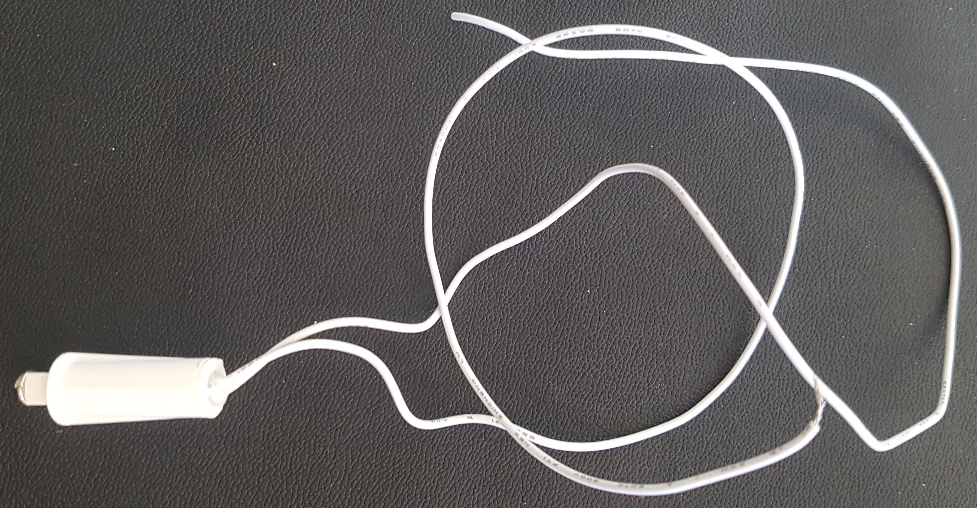
Another question, this part which came with my alarm I find it to be extremely handy that I can use it in different places, I need to find it online and order more.
It's a basic alarm tamper switch. Now my external alarm has its own tamper switch and on board there's a tamper input. I've tried connecting both standalone tamper switch and siren tamper switch to the panel in the tamper input however only 1 of them works at a time. Is there anyway I can get both of them to work individually when triggered?
Thanks you guys again, your assistance helped me configure my alarm myself. Soon I'll start installing and programming it the way I want (:
I use multiple zones as I always have my store room / workshop alarmed even if the house is not.
And then for the house I have seperate zones with varying numbers of sensors in each with some overlap, so I can run; all sensors active or night mode with one PIR disabled so I can get to the bathroom without setting the alarm off at night.
Zones are also useful if you have a granny flat or second area with a second keypad.
Good luck with the sensor turning, my neighbours and I had some early wake up false alarms in the first few weeks :(
There are many reasons for multiple zones & could be a good idea to have each sensor in a separate zone depending on how many you have. Could be useful for determining which areas have been activated, determining which sensors are creating false alarms, etc. A good example would be setting the sensors which are activated by walking to the keypad are set on a delay, whereas sensors which are not activated by walking to the keypad to be set to alarm instantly.
However, if you're wanting to put all sensors into a single zone, you'll have to wire them in series. So effectively creating a loop. In your case, instead of connecting one of the ends of the wire into Z1, you'll want to connect that to one wire from another sensor, and then the other wire into Z1. This video will explain it better - different sensors but same principal for PIRs. Please also note that you'll only need one End of Line Resistor for all the sensors which are connected to that single zone.
The tamper sensor you've mentioned is just a simple switch. If you're wanting to use this for doors, windows, etc, I suggest you look into reed switches - there are different designs depending on where you're wanting to use them (e.g. ones that can be placed in a door frame so more discreet). They can be purchased cheaply from various places like AliExpress, TradeMe, Jaycar.
In regards to getting the tamper to work for both the tamper switch and siren tamper, you'll also need to connect these together in series, the same as for using multiple sensors in a single zone.
Edit: Missed a couple things.
- As default, the alarm will arm all zones when arming, so there's no inconvenience by having each sensor in a different zone.
- For the power to the additional sensors in a single zone, just wire the red and black wires the same as the original sensor into the panel.
- For unused zones, best practice would be to set them as unused when programming the alarm, so no need to put resistors on these. However, putting resistors over the zones would also work (but wouldn't recommend this).
The loop thing makes sense to me I now get it for both PIRs in 1 zone and multiply tamper switchs. It means all these things are in a closed circuit, if any of them (whether PIR or tamper switch) triggers, the closed circuit opens casing alarm to go off.
The reason I want couple of tamper switches is that I want to place one in the electric box outside of the house and maybe another one in MDF. Isn't it smart idea to protect these boxes from people tampering with them? :)
Since it's ideally to hide the alarm box, do you guys recommend put it inside the roof space?
Good idea with the tamper switches, but I'd recommend perhaps putting them in their own zone and not the tamper one as this is a 24 hour zone (meaning the alarm will trigger whenever the switch is activated, opposed to only being triggered when the alarm is armed).
I'd recommend locating the alarm panel in a cupboard or similar. Placing electronics within the ceiling cavity can cause them to fail prematurely due to the high temperatures. However, I've seen a quite a few installs in ceiling cavities with no issues.
Thanks for the tip. You right, better to zone them I don't want them to be 24 hour armed. So in this case I guess 1 wire goes to tamper and 1 wire goes to Z8 for example?
Not quite, one would go to COM & the other Z8. Then you'd program the zone type to be say instant/delay so the tamper switch will be armed when the alarm has been armed.
For the PIR in your case though, from what I can tell in the image, you'd just need to put the black wire into 'GND', and red into '+12'. You should probably use the Tamper terminals in conjunction with the NC though - refer to diagram and image attached.
Not too sure why instructions are suggesting this method, but it does work. I believe it would be PGM, and because the current draw of the piezo is so small, undesired affects aren't likely. It would probably be better to wire it in parallel to the siren though - so on the relay terminal, connecting the piezo to AUX and 1.
I'm not a professional though, so if anyone else could chime in that'd be great!
@nzlogan..please forgive me I edited your diagram :)
This's how I'm going to wire my system tonight. Later once I program the alarm I'll change the tamper to Z5 as you mentioned. I'm starting a simple one for now.
Are you subscribed to our RSS feed? You can download the latest headlines and summaries from our stories directly
to your computer or smartphone by using a feed reader.